

Natural Gas Compressor Station Flow Control
Whether measuring natural gas to fuel the compressor at a compressor station, measure flow at its dry gas seals, or measure blowdown amounts, the thermal mass flow meter provides cost-efficient and accurate measurement solutions.

Compressor Stations
An essential component of the transportation of natural gas is the compressor station. The natural gas compressor station is a facility strategically located along the natural gas pipeline where the gas is compressed to a particular pressure, thereby allowing the gas to continue to flow through the pipe toward its end destination. The number of compressor stations in a pipeline will vary depending on the conditions and region but usually occurs every 40-100 miles. There are approximately 1,650 compressor stations in the United States containing nearly 9000 compressors. Each compressor station will have many components, but the compressor is the heart of the station and the equipment that compresses the gas. The compressor consists of an engine and a compressor. Pipeline gas fuels the engine which powers the compressor.
T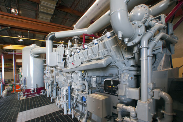 here are several applications at these facilities where thermal mass flow meters excel.
Measure Natural Gas Fuel
The engine used with the compressors are fueled by natural gas from the pipeline, and the natural gas distribution company needs to account for the fuel used to power the compressor. In this application, thermal mass flow meters are ideal for measuring the natural gas flow to the engine as the devices measure mass flow and do not require the added expense of pressure or temperature sensors, as well as a flow computer to determine flow correction. A two-inch pipe is a typical size for this application where the thermal mass flow meter can be installed as an insertion device or as a flanged flow body. The flow meter is easy to install and has no moving parts in the gas stream.
Dry Gas Seal
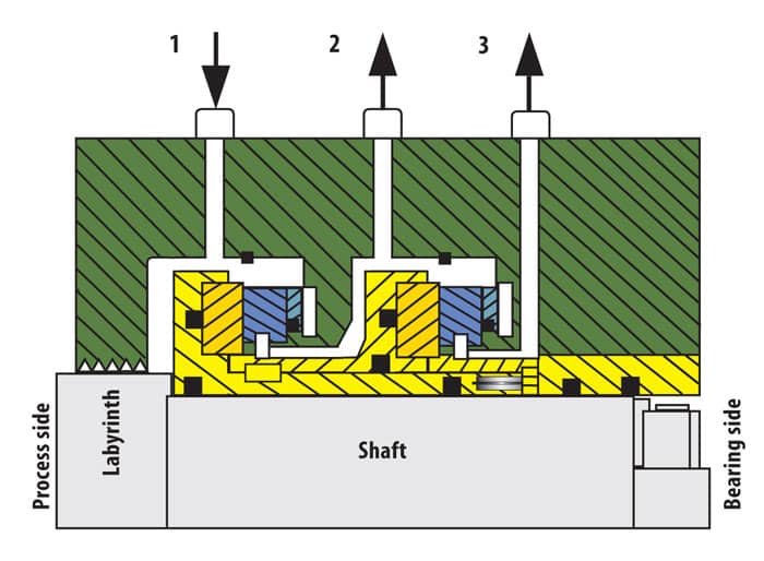 Dry gas seals are non-contacting closures. They are dry-running mechanical face seals that consist of a mating (rotating) ring and a primary (stationary) ring. When operating, elevating geometry in the rotating ring produces a fluid-dynamic drive causing the primary ring to separate. This generates a gap between the two rings. The dry gas seal is a mechanical seal but uses other chemicals and functions so that they do not contaminate a process. These seals are often used in harsh working environments such as compressors for natural gas pipelines, and the tandem seal is widely employed in the industry.
Dry gas seals, as opposed to wet oil seals, are installed on over 90% of new compressors in varied applications, including those compressors routinely used on natural gas pipelines.
Tandem style dry seals consist of a primary seal and a secondary seal contained in a single cartridge. The function of the gas seal system is to prevent leakage of the process gas into the atmosphere. This is accomplished by inserting high-pressure gas between the compressor labyrinth seal and the primary seal. Any leakage gas that passes through the primary seal vents to a flare. An even smaller amount may pass by the secondary seal and vent. However, the main purpose of the secondary seal is to serve as a backup in case of a failure of the primary seal in which case the secondary seal will provide necessary sealing until the compressor can be shut down.
It is desirable to measure the continuous flow of gas from the seals to the flare to determine how much gas vents to the flare. As the seals wear, the amount of gas flow will increase, therefore monitoring the seal gas flow is effective preventive maintenance. The flow of vent gas to the flare is relatively low, often in the range of 5 to 20 SCFM depending on compressor size. A typical pipe size here is 1 inch. The measurement of the seal vent line to the flare may be required for the reporting of greenhouse gas emissions to meet EPA requirements. (Refer to Sage white paper, “Greenhouse Gas Emissions Monitoring Using Thermal Mass Flow Meters.”
Blowdown
During normal operation of the compressor station, there are times when the compressor may have to startup or shutdown. Pressurized natural gas remains in the compressor and adjoining pipeline during this stage. In some instances it may be necessary to release or blowdown this gas; often this may be accomplished by venting the gas to an adjacent compressor. On other occasions, it may be needed to vent this gas to the flare. During the blowdown period, the pressure and flow rate in the blowdown piping will vary considerably.
Considerations for Flow Meter Selection

- Mass flow measurement without the need for temperature and pressure correction
- Easy in-situ calibration verification method to verify the accuracy and operation of the sensor and transmitter
- Wide turndown for precision measurement at low or high flow
- With varying gas pressures and flow rates, the thermal mass meter has excellent low flow sensitivity and negligible pressure drop
- Easy installation
- Approved for use in hazardous area
Recommended Sage Models for this Application
Sage Prime
Sage Paramount