Here is an updated online version of the 2015 white paper, “ISO 50001 Energy Management: The Use of Thermal Mass Flow Meters in ISO 50001 Energy Management Systems.” This paper explores using thermal mass flow meters to measure and monitor natural gas and compressed air to improve energy efficiency.
The Use of Thermal Mass Flow Meters in ISO 50001 Energy Management Systems
 Introduction
With the introduction of ISO 50001, industrial plants, governmental agencies, and commercial and institutional facilities implement continual energy management systems. These systems are designed to improve energy efficiency. The ISO standards require a facility to adopt an energy policy and follow a four-step model to implement change while continuously monitoring to improve the process.
Natural gas and compressed air are commonly used in facilities implementing energy management systems. Thermal mass flow meters (TMFMs) may measure natural gas consumption at different locations in the facility and individual combustion sources. The Department of Energy estimates that 20-30% of compressed air is lost due to leakage, and TMFMs are routinely used in compressed air measurement applications. Additionally, with an emphasis on energy management, many facilities retain the services of energy monitoring specialists to conduct energy audits. These firms may use portable flow meters during audits to measure energy consumption.
If you want a PDF version of the original paper, download it now.
ISO 50001
What is ISO?
ISO is the International Organization for Standardization. It is the leading developer of voluntary International Standards, which provide advanced specifications for products, services, and practices to be safer, cleaner, and more efficient. The standards are generated, through international agreements, to promote the international exchange of products and services. Established in 1947, ISO has published nearly 20,000 standards impacting most industries worldwide. Some of the established groups of measures include:
- ISO 9000: Quality management – Ensures products and services meet customers’ needs
- ISO 14000: Environmental management – Improves environmental performance
- ISO 3166: Country codes help avoid confusion when discussing countries and their subdivisions
- ISO 22000: Food safety management – Helps consumers instill confidence in food products
- ISO 26000: Social responsibility – Helps organizations operate in a socially responsible manner
- ISO 31000: Risk management – Helps manage risks that could negatively affect a company’s performance
- ISO 4217: Currency codes – Helps avoid confusion when referring to world currencies
- ISO 639: Language codes – Helps describe languages in an internationally-accepted approach
- ISO 20121: Sustainable events – Manages social, economic, and environmental impacts of events
- ISO 27001: Information security – Ensures an organization’s information is safe
- ISO 50001: Energy management – Focuses on energy savings by making organizations more efficient
What is ISO 50001 Energy Management?
ISO 50001 is a voluntary international standard that provides organizations with energy management systems (EnMS). ISO defines an energy management system as a “set of interrelated or interacting elements to establish an energy policy and energy objectives, and processes and procedures to achieve those objectives.”
The model was formerly known as ISO 50001:2011, Energy management systems – Requirements with Guidance. The energy management systems within ISO 50001 establish a template for industrial plants, governmental agencies, and commercial and institutional facilities. The model provides a framework for organizations to use when pursuing their goals to improve energy efficiency.
Energy management systems serve large and small organizations worldwide, whether owned publicly or privately. With energy being a significant expense in most organizations, ISO 50001 provides organizations with strategies to reduce energy use to save energy costs and reduce greenhouse gas emissions.
ISO 50001 was released in June 2011 and is modeled after other standards, including ISO 9001 (quality management), ISO 14001 (environmental management), ISO 22000 (food safety), and ISO/IEC (information security). According to the Department of Energy, while ISO 50001 certification is not required in the United States, many U.S. manufacturing facilities and commercial buildings implement ISO 50001 through Superior Energy Performance (SEP) programs.
Superior Energy Performance
SEP is the U.S. certification program directed by the Department of Energy to certify increased energy productivity under ISO 50001. Many U.S. facilities had implemented SEP energy management systems before the 50001 approval. Participation in the SEP program now requires implementation and certification of ISO 50001. According to SEP, the first SEP-certified facilities have achieved the following:
- Annual savings ranging from $87,000 to $984,000 using no-cost or low-cost operational measures
- On average, there is a 10% reduction in energy costs within 18 months of the SEP implementation.
- Over three years, in a wide range of industries, there has been a 6% to 25% energy performance improvement.
- Facilities having energy costs of over $1.5M annually were able to achieve paybacks in less than two years.
In addition to SEP figures, Subaru of Indiana Automotive (SIA), one of the first companies to implement 50001, realized over $550K in energy savings in 2012 and over $600K in 2013. Brent Lank, from SIA, shared his lessons learned while Subaru went through the process. “For ISO 50001 to work, it is imperative that you not only understand how much energy is being used, but where that energy is being used, what is using it, and by using the defined variables, understanding how well you are using that energy.”(1)
EnMS Metering and Monitoring Equipment
“The SEP program requires that facilities meter, monitor, and record energy consumption data for identified significant energy uses (SEUs) and the facility as a whole. In most cases, the establishment used utility revenue meters and a mix of preinstalled and new sub meters for their SEUs.”(3)
ISO 50001 Objective
The primary goal of ISO 50001 is to improve energy-related processes and efficiency. Improving efficiency, of course, saves money and helps improve the environment by reducing greenhouse gases.
The Improvement Process
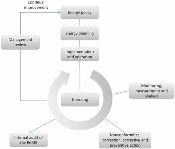
The ISO 50001 process is based upon a continual improvement management system which is used in other standards, ISO 9001 and ISO 14001, and follows a PDCA cycle (Plan-Do-Check-Act), which is a four-step model used to carry out change while continuously monitoring to improve the process. (2)
Conduct the energy review and establish the baseline, energy performance indicators, objectives, targets, and action plans necessary to deliver results in accordance with opportunities to improve energy performance and the organization’s energy policy.
Do
Implement the energy management action plans.
Check
Monitor and measure processes and the key characteristics of its operations that determine energy performance against the energy policy and objectives and report the results.
Act
Take actions continually to improve energy performance and the energy management systems.
ISO 9001:2008 Calibration and Maintenance Requirements
ISO 9000 is a group for some of ISO’s most recognized standards associated with quality management. These standards help organizations ensure that their products and services consistently meet customers’ requirements while continuously enhancing quality.
ISO 9001 requires that all equipment used in measuring or monitoring processes needs to be maintained and calibrated. These calibrations must be routinely performed as determined by engineering.
ISO 14000 – Environmental Management
ISO 14000 is a collection of standards associated with aspects of environmental management. These standards help organizations and companies involved in minimizing their environmental impact. ISO 14001:2004 and ISO 14004:2004 incorporate environmental management systems.
Applications for Thermal Mass Flow Meters
Typical applications for using TMFMs in energy management include combustion control, natural gas utilization, and compressed air monitoring. These applications have a widespread impact as they are used in many heavy industrial operations, including textile, glass manufacturing, automotive, aluminum & steel, food & beverage, pulp & paper, power, chemical, and refining. They are also found in many light-duty industrial and commercial operations, such as universities, hospitals, and building complexes.
Compressed Air
Where is Compressed Air Used?
Compressed air is often used in industrial facilities and is often referred to as the “fourth” utility behind natural gas, electricity, and water. The cost of compressed air on a unit per energy delivered basis is more expensive than other utilities(4), and it is also one of the most inefficient energy resources.
Compressed air is used in pneumatics (including air tools, HVAC control systems, and pneumatic posts), vehicle propulsion, refrigeration systems, engine air-start systems, conveying, controls and actuators, automated equipment, and spraying cooling.
Compressed Air Flow Monitoring
Compressed Air Leaks
The Office of Industrial Technologies (OIT) develops advanced energy efficiency, renewable energy, and pollution prevention technologies for industrial applications. OIT has cited that compressed air leaks are a significant source of wasted energy, often wasting up to 30% of the industrial compressor’s output.
While leaks may be in any part of the compressed air system, they are more prevalent in condensate traps, couplings, filter-regulator assemblies, fittings, flanges, hoses, packing, pipe joints, point-of-use devices, quick disconnects, thread sealants, tubes, or valves.
Compressor air leaks increase the compressor output, which raises the cost of producing the compressed air. The leaks also cause irregular line pressure that can cause air-operated tools and equipment to operate less efficiently, impacting productivity. Additionally, the leakage can increase maintenance costs and reduce the equipment’s service life, including the compressor, because of unnecessary cycling and extra runtime.
Eliminating Compressed Air Leaks
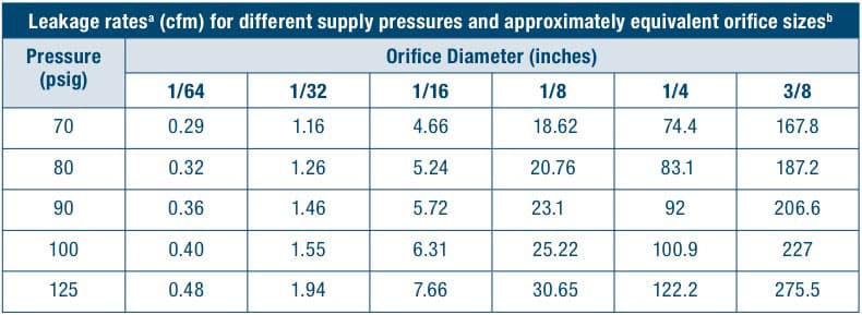
For well-rounded orifices, values should be multiplied by 0.97 and by 0.61 for sharp ones, used with permission from Fundamentals of Compressed Air Systems Training offered by the Compressed Air Challenge®.
The opportunity to save energy costs by eliminating compressor leaks is considerable. Using Figure 1, we can determine the extent of compressed air lost through each leak. For example, let us assume a manufacturing plant with a conventional compressor system running at 100 PSI with ten ¼” leaks. Each tiny hole would pass 100.9 CFM of wasted compressed air in this situation. Assuming the site has 7000 working hours per year, an average electric rate of $0.09kWh, and a compressed air generation requirement of 18 kilowatts (kW)/100 cfm, the facility could save nearly $70,000 by repairing the ten small leaks.
Cost savings = number of leaks x leakage rate (cfm) x .61 (Factor for sharp leaks) X (kW/100cfm) x number of hours operating x $/kWh
Cost savings from ten 1/4” leaks = 10 holes x (100.9 CFM x 0.61) x (18kW/100CFM) x 7,000 hours x $0.09/kW/h = $69,797 per year
Methods to Identify Air Leaks
There are a few ways to detect compressed air leaks.
Ultrasonic Acoustic Detector
When pressurized air or gas escapes through any opening, a pressure change results in a hissing sound. This high-frequency noise is in the ultrasonic spectrum. The ultrasonic acoustic detector is a portable device that can detect this type of leak. Though some models are problematic in noisy environments, these meters are usually easy to use, and costs and sensitivities vary depending on the manufacturer.
Gas Leak Detection Compound
Leak detection compounds are solutions (similar to dish soap) that pinpoint pressurized air or gas leaks when applied with a paintbrush or dauber. While the compounds are usually cost-effective, using this technique in suspected areas is time-consuming and messy.
Thermal Mass Flow Meters
While the previous two methods pinpoint the location of the leaks, TMFMs can determine if there is a leak, or leaks, in the system and quantify the wasted energy. A thermal flow meter is inserted at various points of a pressurized compressed air line, preferably following an air dryer, since moisture can interfere with the flow measurement. A signal of compressed air flow rate is produced that is not affected by changes in air pressure. In this case, airflow is constantly measured while the facility is manufacturing and during off shifts and weekends.
The amount of compressed air a plant uses depends on the work schedule. There is more consumption during production and less during off shifts (nights and weekends). If the production stops, the compressed air used is due to leakage or failure of the operator to shut down their equipment.
This flow rate variation creates difficulties for some flow meters with limited turndown capabilities (differential pressure measurement). TMFMs can easily measure these wide variations in flow rate.
Portable TMFMs, such as the Sage Prism®, can periodically monitor the system’s flow usage to determine either consumption or compressor efficiency.
Compressed Air System Audits
There are independent companies that specialize in compressed air system audits. These businesses conduct audits for facilities, large and small, and include leak surveys of compressed air systems. Those organizations interested in determining energy consumption may have compressed air system audits. In these cases, portable TMFMs that are easy to use are desired by compressed air specialists. Portable flow meters can be battery-operated to measure flow in various locations at a given time. During long-term continuous flow monitoring, the user can also plug the meter in for electrical power. A portable flow meter should record and store the flow data, which can then be downloaded to a spreadsheet for analysis and permanent records. The Sage Prism can either automatically check and record a data point at a predetermined sample period or manually test when desired. The Prism has sufficient memory to record a sample every ten seconds for two weeks on a long-term audit. The time and date are recorded for each data point, along with the flow rate, gas temperature, and channel description.
Compressed Air Flow Measurement
TMFMs can be installed in individual lines to determine where the compressed air is used and determine the relative leakage. In many facilities, the compressed air usage may vary considerably, with the highest flow occurring during the day and significantly reduced airflow at night or on weekends. TMFMs provide a direct mass flow measurement, are easy to install into a pipe with minimum piping modifications, and can easily handle the wide fluctuations in compressed air flow that may occur.
Sage Metering provides easy-to-install insertion TMFMs for standard compressor lines and offers a convenient isolation assembly valve for mounting. These flow meters measure gas mass flow based on heat transfer from a heated sensor into the gas flow stream. Direct measurement of mass flow is obtained without separate temperature or pressure measurements. In addition, the transmitters have no moving parts, are highly accurate and repeatable, and have negligible pressure drop. Sage TMFMs have extraordinary rangeability of at least 100 to 1, as well as a rapid response. Additionally, Sage meters are digitally driven, resulting in exceptional low-end sensitivity without sacrificing performance at the upper end. Sage flow meters, with sensitivity as low as 5 SFPM (1 SCFM in a 6” pipe), permit leak detection by assessing whether compressed air lines, thought to be unused, are wasting expensive air through undetected leaks.
Sage flow meters have 4 – 20 mA outputs of flow rate and pulsed outputs of consumption and provide complete Modbus-compliant RS485 RTU communications, which are all ideal for advanced energy management systems. The meters also feature bright graphical displays of flow rate, a non-resettable totalizer (often a requirement for Environmental reporting), a temperature reading, plus continuous diagnostics. For hard-to-reach pipes or locations with extreme radiant heat, Sage also offers a remote-style flow meter with up to 1000 feet of lead length compensated cable – all electronics and powering are accomplished at the transmitter – thus, the probe has a terminal junction box.
Natural Gas Measurement
In today’s world, energy consumption and improving efficiency are top objectives for most facilities. The first step to improving efficiency is establishing a baseline by determining the natural gas consumption, and TMFMs are ideal for this application.
Natural Gas Efficiency
Combustion sources may have different efficiencies, and when measuring the natural gas flow rate at the source, one can learn which operation is more efficient. A TMFM is an ideal device for measuring natural gas flow rates to various combustion sources.
Natural Gas Submetering
With a goal for energy conservation, it is necessary to monitor natural gas mass flow rate and consumption at individual zones. Submetering helps allocate costs to various operating areas, thereby assisting the facility energy manager in identifying high-consumption areas to focus on for efficiency improvement. Secondarily, submetering helps determine process efficiencies, identifies unusual consumption points, and promotes conservation. Typical applications for natural gas submetering are in various industries, including textile, glass manufacturing, automotive, aluminum & steel, and food & beverage.
Combustion Efficiency
One of the most noteworthy methods to reduce energy consumption in a manufacturing environment is to optimize the combustion control of industrial boilers, steam generators, furnaces, ovens, and process heaters. The optimal air-to-fuel ratio can be achieved by monitoring the air and fuel rates to the burners. This results in a significant reduction in energy costs of natural gas (or propane) and also improves process efficiency, product quality, and yields. As part of an overall strategy, many local and state-wide jurisdictions have environmental regulations that require flow meters on all medium and large-size combustion sources to report plant-wide emissions. Typical applications for combustion control monitoring are found in various industries, including textile, glass manufacturing, automotive, aluminum & steel, food & beverage, pulp & paper, power, chemical, and refining.
Combustion control monitoring is also conducted in small boilers in hospitals, large buildings, universities, and similar structures. Refer to the white paper, “Combustion Efficiency and Thermal Mass Flow Meters,” by Sage Metering for a more in-depth look at saving energy through combustion efficiency.
Greenhouse Gas Emissions Monitoring
With increasing pressure from society regarding environmental concerns, along with local, international, and government mandates concerning greenhouse gas (GHG) emissions, there is a need to measure and monitor greenhouse gases accurately. While this paper pertains to energy efficiency, ISO 14000 involves environmental management to improve performance and provides a framework to systematize and enhance environmental management efforts. There is a wealth of information about using TMFMs in monitoring greenhouse gas emissions from combustion sources and for biogas, landfill gas, digester gas, and flare gas applications in “Greenhouse Gas Emissions Monitoring Using Thermal Mass Flow Meters.”
Building Management Systems
TMFMs are often employed in building management systems for climate control. Insertion-style TMFMs for larger natural gas lines and in-line thermal flow meters for smaller gas lines monitor and control inlet flow to boilers, furnaces, and heaters. Building management systems are in apartment buildings, high rises, governmental facilities, sizeable industrial production environments, campuses, shopping centers, and other facilities. The building management system continually maintains a comfortable indoor temperature while at the same time minimizing the energy required in doing so.
Natural Gas Flow from the Main into the Plant
With ongoing concern for energy consumption, monitoring the instantaneous natural gas mass flow rate coming into the plant is essential because it provides information about its natural gas demand. The customary billing meter only reports consumption over a fixed period (i.e., monthly). A TMFM monitors flow rate as well as consumption. It also provides real-time feedback on normal operating conditions, peak demand, inefficiencies, and wasted energy.
Sage Natural Gas Flow Meter
Compared to other flow measurement technologies, the Sage TMFM obtains mass flow measurement without needing temperature and pressure correction. The Sage meters provide excellent rangeability, extraordinary low flow sensitivity, and do not have any pressure loss. In addition, the insertion probe is easy to install directly into the pipe. Other flow meter types may require a reduction in pipe size to achieve the desired operating range, substantially increasing installation costs.
Energy Audits and Monitoring
Energy Audits
There is a growing demand across all industry sectors to conserve energy, not only from the energy cost standpoint but also because of environmental sustainability. Engineering organizations specialize in energy audits and monitoring. Audits are performed to identify facility improvement opportunities and develop energy management strategies. These assessments provide an understanding of the baseline energy consumption that can provide guidelines for improvement in production efficiency and identify cost reduction opportunities in energy efficiency.
Energy audits inspect the facility’s heating, cooling, and lighting systems, water and steam consumption, ventilation, and control systems. Process energy is often included in manufacturing and production facility audits.
Portable TMFMs are used by energy audit companies when conducting energy audits or compressed air surveys. Unlike pitot tubes, which are used in the flow measurement of natural gas or compressed air, or any other volumetric flow device, a TMFM has the advantage of direct mass flow measurement without pressure and temperature correction, wide sensitivity, and automatic data logging rather than the manual entry of the flow data.
Prism Thermal Mass Flow Meter
The Sage Prism has been discontinued.
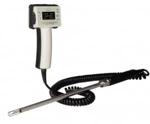
Portable Thermal Mass Flow Meter with Data Logging
Sage Prism was the industry’s first portable battery-operated data-logging TMFM. It was initially introduced in 2010. In 2015, significant improvements were introduced to the design and operation to respond to customers’ feedback. The updated Prism has multiple channels, which can be configured for various applications. A software program (PC) is used to configure the flowmeter with a descriptive channel name, pipe size, units of measurement, and flow range. In addition, the gas composition can be entered, and the Prism automatically makes appropriate adjustments, which is particularly advantageous when measuring landfill gas, digester gas, or biogas where the ratio of methane to CO2 varies.
The new Prism can record up to 130,000 data points, continuously permitting flow rate sampling every ten seconds over two weeks. The information can be downloaded to any spreadsheet for analysis and recording. Each data point includes a channel name, date, time, flow rate, and temperature. The improved design allows the user to operate the Prism using an external power supply if the meter exhausts its ten-hour battery life. The Prism has 12 channels that provide maximum flexibility, and each can be configured to pipe size, units of measurement, Tag ID, or variations in gas composition. In addition, there are four factory-set channels. The channels are easily configured with the included and easy-to-use Sage Prism Configuration Software (SPCS). The software also facilitates downloading data into comma-separated values (CSV) files for further use in a spreadsheet and data management. Once downloaded from the Prism, SPCS displays the flow data in numeric and graphical format.
Calibration Verification
The Sage TMFM is fully calibrated at the factory using our NIST-traceable calibration facility. Through straightforward no-flow calibration verification, it is possible to verify quite easily that the flow meter maintains its original factory calibration.
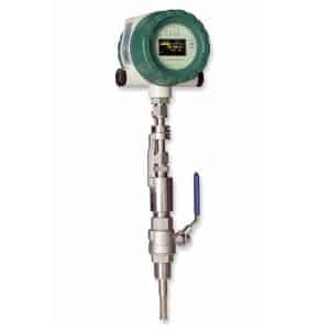
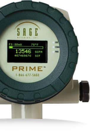
For the Sage Prime®, the user can perform the calibration check if a “no-flow” (0 SCFM) condition is created. “No flow” is created using an isolation valve assembly with the insertion style meter (See Figure 2). Unlike other TMFMs, the Sage In-Situ Calibration verifies that the unit is accurate and indicates that the sensor is clean. If the meter does not pass the calibration test the first time, in most cases, cleaning the sensor and re-testing confirms that the meter is accurate and has not drifted or shifted. Read “Thermal Mass Flow Meter Onsite Calibration Check” or our brochure for more information on this unique calibration verification method.
During manufacturing, the Sage Zero Chamber facilitates recording the “no flow” signal data point while subjecting the meter to the customer’s specified conditions (i.e., the gas or gas composition and pressure). The “no flow” data point is one of many data points used for the flow meter’s NIST traceable calibration and is a suitable standard for the calibration check. This information is conveniently recorded on the meter’s tag and also on the Certificate of Conformance. The “zero flow” signal data point is provided for the specified gas at indicated operating conditions or for air if the user wants to perform this test elsewhere than in the piping.
Traditionally, TMFMs have relied upon the analog Wheatstone bridge electronic circuit, which is likely to drift. One of the unique elements of Sage’s approach is the ability to use a digital method of driving the sensors in place of the Wheatstone bridge. The proprietary technology provides additional benefits, which include improved signal stability, enhanced temperature compensation, better sensitivity to detect flow changes, improved resolution, and the ability to adjust the meter’s operating range to match the client’s specific operating conditions. These inherent features allow the Sage TMFM to perform the in-situ/no-flow calibration verification.
ISO 9001 requires that all equipment used in measuring or monitoring processes needs to be maintained and calibrated. These calibrations must be routinely performed as determined by the quality assurance procedure.
Other TMFM manufacturers have recognized the need for some method to verify the calibration of their meters. Following the introduction of the Sage In-Situ Calibration verification, other meter manufacturers introduced their options. One manufacturer requires expensive supplementary hardware. Another company promotes a process that verifies the electronic’s work, though it does not check the sensor performance nor verify that the meter is calibrated. Other manufacturers require that the meters be taken offline and returned to either the manufacturer or a third party for annual recalibration.
Sage’s In-Situ Calibration verification process is straightforward and can be performed easily and inexpensively in the pipe or duct. The process verifies that the sensor and electronics are correctly functioning, eliminates the need for factory recalibration, and meets ISO 9001 requirements.
Conclusion
ISO 50001 provides voluntary standards for industrial plants, governmental agencies, and commercial and institutional facilities interested in using energy management systems to improve energy efficiency, save on energy costs, and minimize the environmental impact of greenhouse gases. These are continuous processes in which measurement and monitoring equipment are required to establish baseline energy consumption and then continually measure and monitor the actual usage.
TMFMs are proper measurement instruments for ISO 50001 energy management systems. They can measure natural gas consumption at different facility parts and individual combustion sources. They are also effective at measuring compressed air and can help determine and monitor compressed air leakage. Additionally, energy monitoring specialists can use portable TMFMs, such as the Sage Prism, when performing energy management audits or simply quickly checking the flow rate in the pipe. Furthermore, the Sage meters comply with the calibration requirements within ISO 9001.
References
(1) A Look at Energy Management at Subaru of Indiana Automotive .., http://www.energymanagertoday.com/a-look-at-energy-management-at-subaru-of-india (accessed April 9, 2014).
(2) Peter Therkelsen, Ridah Sabouni, Aimee McKane, and Paul Scheihing. (2013). Assessing the Costs and Benefits of the Superior Energy Performance Program, 2013 ACEEE Summer Study on Energy Efficiency in Industry, Niagara Falls, NY http://superiorenergyperformance.energy.gov/pdfs/sep_costbenefits_paper13.pdf
(3) ISO 50001:2011(en) Energy management systems — Requirements with guidance for use, https://www.iso.org/obp/ui/#iso:std:iso:50001:ed-1:v1:en (accessed February 18, 2014).
(4) (Wikipedia Reference) Yuan, C., Zhang, T., Rangarajan, A., Dornfeld, D., Ziemba, B., and Whitbeck, R. “A Decision-based Analysis of Compressed Air Usage Patterns in Automotive Manufacturing,” Journal of Manufacturing Systems, 25 (4), 2006, pp.293-300
Sage Metering References
- Compressed air “Win the energy challenge with ISO 50001,” ISO 2011-06/3 000, International Organization for Standardization, ISBN 978-92-67-10552-9
- Natural Gas Flow Measurement and Monitoring Using Mass Flow .., https://sagemetering.com/applications/energy/natural-gas-flow-measurement/ (accessed March 13, 2014).
- Greenhouse Gas Emissions Monitoring Using Thermal Mass Flow .., https://sagemetering.com/knowledge-base/topics/greenhouse-gas-emissions-monitorin (accessed March 13, 2014).
- Combustion Efficiency and Control Using Thermal Mass Flow Meters, https://sagemetering.com/knowledge-base/topics/combustion-efficiency-and-thermal- (accessed March 13, 2014).
- Air Flow Meter for Combustion Efficiency of Industrial Boilers, https://sagemetering.com/blog/combustion-efficiency/air-flow-meter-for-combustion (accessed March 13, 2014).
- Thermal mass flow meters for greenhouse gas monitoring .., https://sagemetering.com/blog/sage-metering-news/thermal-mass-flow-meters-for-gre (accessed March 13, 2014).

