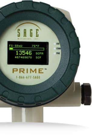
This post compares leading thermal mass flow meter manufacturers’ in-situ calibration methods, revealing only one convenient and accurate process.
Factory Calibration
Thermal mass flow meters are factory-calibrated to correlate the operating power to mass flow. Since the calibration requires a NIST traceable flow instrument, the end-user can’t calibrate a thermal flow meter in the field. For this reason, the end-user must return the meter to the manufacturer for periodic recalibration. This process can be time-consuming and expensive and even requires purchasing a second flow meter to swap out the meter being re-calibrated.
Regulatory Influence for On-Site Calibration
Many companies have internal laboratories to maintain their equipment, including calibrating instruments on the premises. This setup is partly driven by regulatory mandates that require users to calibrate their flow meters periodically when measuring and reporting greenhouse gas emissions. More information is available in our white paper, “Greenhouse Gas Emissions Monitoring Using Thermal Mass Flow Meters.”

Sage Metering compares thermal mass flow meter manufacturers’ calibration verification methods, revealing only one convenient, accurate, and in-situ choice.
Available In-Situ Calibration Methods
Thermal mass flow meter manufacturers have responded to the industry’s need for a method to verify, while in the field, that their flow meters are calibrated and accurate. In a perfect world, the manufacturer’s verification method checks the sensor and transmitter while the meter is still in the pipe. Currently, thermal mass flow meter manufacturers offer the following techniques:
Sage Metering Option
In the Sage Metering In-Situ Calibration Verification, the user withdraws the sensor from the pipe into an isolated chamber where a no-flow condition exists. They compare the zero-flow mW signal on the flow meter’s display with the original calibration data printed on the flow meter’s nameplate.
Advantages – No special equipment is required, and the end-user can perform the in-situ test while in operation. The method examines both the sensor and the electronics. It verifies that the operating zero-flow data matches the calibration curve; any offset at no-flow will reflect in the entire curve. If the zero-flow data matches the original calibration data, the test assures the user that the performance has not shifted.
Disadvantages – None
Competitor #1
One manufacturer approaches the challenge by removing the sensor from the pipe and positioning it within a specialized compartment, isolating the sensor from the flow. Then, a known amount of reference gas from an external bottled source flows past the sensor. This step repeats multiple times, and the data is compared to the initial factory calibration data.
Advantages – This method checks both the sensor and transmitter against a known reference.
Disadvantages – The process requires the purchase of expensive hardware, and it cannot add the equipment later. It is also cumbersome and requires initial factory calibration data on both the process and reference gases.
Competitor #2
Another manufacturer’s method requires that the unit be taken out of service, though it stays in the pipe. The flow signal from the sensor is isolated, and an external signal is simulated. The sensor elements signal (power) is varied, and the transmitter evaluates the electrical output, which will generate a pass or fail message.
Advantages – This method requires no extra hardware, and the user can perform it on-site.
Disadvantages – Unfortunately, it only tests the electrical signal and electronics. It does not check the sensor’s operation or if the sensor is clean. One of the common difficulties for flowmeters in industrial environments is the buildup on the sensor.
Competitor #3
In a third manufacturer’s test, the user removes the meter from the pipe, the sensor is isolated, and the transmitter connects to a computer. The computer sends the flow meter a known signal and confirms that the transmitter output matches the expected value. Of course, this requires a computer and the purchase of specialized software.
Advantages – There are no clear benefits to this method.
Disadvantages – This procedure only tests the electronics, verifying that the output matches the calibration curve. It does not check the sensor operation or if the sensor has drifted.
Competitor # 4
In another manufacturer’s method, the end-user removes the meter from the pipe and tests the sensor under no-flow and a simulated high-flow condition using a water bath. The user then compares the results to the original calibration data.
Advantages – In this procedure, both the sensor and electronics are tested at known values.
Disadvantages – The downside is that the end-user must remove the thermal mass flow meter from the pipe.
 Conclusion
Suppose the objective of an on-site calibration verification is to validate that the meter is accurate and that the sensor and transmitter perform correctly. In that case, only Competitors 1, 4, and the Sage Metering Option meet the criteria. If we stipulate that the end-user does not have to remove the meter from the pipe and no extra hardware needs to be purchased, only the Sage Metering Option fulfills the requirements.
Out of the methods presented, the Sage In-Situ Calibration Verification is the only procedure where the meter does not have to be removed from the pipe. It is easy and quick and verifies both the sensor’s performance and transmitter.
Reference
Sage Metering, Inc. 8 Harris Court, Bldg. D1. (n.d.). Retrieved from https://www.sagemetering.com/pdf/Understanding_the_Sage_Metering_Calibration_Verification.pdf_br
New Video on In-Situ Calibration
Watch and listen as I explain the Unique Sage Metering In-Situ Calibration method.


