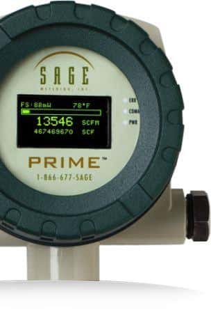
In the second blog on flowmeter analog wiring communications, I answer the FAQ, “What is the wiring configuration for providing internally-powered pulsed outputs for the Sage Prime?”
What is the wiring configuration for an internally powered pulsed output for the Sage Prime?
On the back of the Sage thermal flow meter, there are three vertical columns of terminals identified as A, B, and C terminals (left to right). Each of these columns has six terminals, the top being #1, and bottom #6 with the centers designated by numbers (2-5).
- Hook up the AC or DC power to the meter.
- Connect the ground wire (usually black) to terminal C6
- Connect the pulse return wire (usually red) to the C4 terminal.
- Connect your device for measuring pulse outputs.
Each customer’s pulse rate is set to the client’s specification, so consult your engineer or accompanying paperwork to determine the pulse intervals. If you have any questions or concerns, call us at (866) 677-7243.
Flow Meter Wiring Video
In the following video, I demonstrate how simple it is to wire the pulse output from the thermal mass meter.
FAQ – How to wire a Sage mass flow meter with a 4-20mA output?

