

Here is an updated online version of the 2013 white paper, “Greenhouse Gas Emissions Monitoring Using Thermal Mass Flow Meters,” by Bob Steinberg.
Introduction
With increasing pressure from society regarding environmental concerns and international and government mandates concerning greenhouse gas (GHG) emissions, there is a need to measure and monitor greenhouse gases accurately. This paper explores monitoring greenhouse gas emissions using thermal dispersion or thermal mass flow meters (TMFMs) in monitoring biogas, landfill gas, digester gas, and flare gas.
If you want a PDF version of the original paper, download it now.
New Regulations to Measure GHG
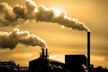
Rising levels of GHG and byproducts have been linked to the cause of global warming. Some GHG emissions are created from industrial processes and everyday living habits of the seven billion plus people on our planet.
 Industrial nations from all over the world now recognize that climate change issues are associated with global warming. In 1997 the Kyoto Protocol was first adopted, in which many countries committed voluntarily to the reduction of four greenhouse gases: carbon dioxide (CO2), methane (CH4), nitrous oxide (N2O), sulfur hexafluoride (SF6), as well as two byproduct gas groups: hydrofluorocarbons and perfluorocarbons. While the United States rejected the Kyoto Protocol, the U.S. Environmental Protection Agency (EPA) has issued strict policies and regulations to reduce greenhouse gas emissions.
When the Kyoto Protocol was ratified, a demand for CERs was created. CERs are more commonly known as carbon credits. A carbon credit is a license for the credit holder to produce one ton of carbon dioxide. Credits are only awarded to those parties or organizations that reduce GHG below a specific quota. Those parties which lower emissions can sell their credits to gas emission emitters which may be countries, large commercial entities, or power generators.
The EPA, responding to the Consolidated Appropriations Act 2008, released the Mandatory Reporting of Greenhouse Gases Rule (74 FR 56260), which requires owners and operators of United States facilities emitting 25,000 metric tons or more of GHGs each year to monitor and measure GHGs and report other pertinent information to the EPA. The information is to be used to assist in future policy decisions. This regulation is commonly referred to as 40 CFR Part 98, while its implementation is known as the Greenhouse Gas Reporting Program (GHGRP).
According to the first released data through the program, in 2010, over 5,500 U.S. emitters met or exceeded the minimum threshold of 25,000 metric tons of CO2e (carbon dioxide equivalent).
Every gas has a different capacity to heat the atmosphere, known as global warming potential (GWP). CO2 has become the standard to which other gases are compared and has a GWP of 1. When GHG data is reported, it is reported as though it is the equivalent of CO2 (CO2e or carbon dioxide equivalent).
| Greenhouse Gases | GWP |
| Carbon Dioxide (CO2) | 1 |
| Methane (CH4) | 21 |
| Nitrous Oxide (N20) | 310 |
EPA 40 CFR 98 accuracy requirements for measuring GHGs vary depending on the subpart. However, 5% is typical. Additionally, 40 CFR 98 requires that flow meter calibration be periodically verified per the manufacturer’s recommendations.
Mass Flow Measurement
Flow Measurement Technologies
Many flow technologies can be used for GHG monitoring, the main ones noted below.
Coriolis flow meters provide a direct mass flow measurement based on the deflection force of the fluid moving through a vibrating tube.
Advantages: very accurate with high turndown capabilities, independent of fluid properties
Disadvantages: costly to purchase and install and has significant pressure drop. Also, not suitable for larger pipe sizes
Differential Pressure flow meters calculate the flow by measuring the pressure drop over an obstruction inserted in the flow. Common types of flow elements are Orifice Plates, Flow Nozzles, and Venturi Tubes.
Advantages: commonly accepted method of flow measurement
Disadvantages: limited turndown, poor low flow sensitivity, requires pressure and temperature measurement to get mass flow
Positive Displacement meters require fluid to displace components and measure volumetric flow mechanically.
Advantages: good accuracy
Disadvantages: because of the moving parts, its use is limited to clean dry gases, requires pressure and temperature compensation
Thermal Mass Flow meter measures mass flow based on heat transfer from a heated element.
Advantages: not affected by changes in pressure or temperature. It has excellent repeatability, no moving parts, and is easy to install.
Disadvantages: none
Turbine Flow meters measure volumetric flow based on fluid flowing past a free-spinning rotor; each revolution corresponds to a specific fluid volume.
Advantages: high turndown and accuracy
Disadvantages: because of the moving parts, its use is limited to clean, dry gases only, requires pressure and temperature compensation
Ultrasonic Flow meters measure the difference in transit time of pulses that travel from a downstream transducer to the upstream transducer, compared to the time from the upstream transducer back to the downstream transducer.
Advantages: extremely accurate
Disadvantages: expensive, require pressure and temperature measurement
Vortex Flow meters operate by pacing an obstruction, a bluff object, or a shedder bar in the flow path. As gas flows around this shedder bar, vortices are cyclically generated from opposite sides of the bar. The frequency of vortex generation is a function of the gas velocity.
Advantages: frequency of vortex shedding is independent of fluid composition
Disadvantages: requires pressure and temperature compensation, requires minimum flow rate to generate vortices
Thermal Mass Flow Meters Excel
Each flow meter technology has its unique advantages and disadvantages. When evaluating technologies for GHG monitoring, thermal dispersion or thermal mass flow meters excel in key areas:
- The TMFM measures mass flow and is not impacted by changes in temperature and pressure; therefore, there is no need for separate temperature or pressure transmitters
- TMFMs offer high accuracy and repeatability
- TMFMs offer excellent rangeability with over 100 to 1 and resolutions as much as 1000 to 1
- TMFMs have no moving parts
- TMFM are easy to install by insertion into a pipe
- The SAGE meter offers an easy onsite in-the-pipe calibration verification
- The TMFM offers negligible pressure drop; therefore, it doesn’t impede the flow or waste energy
- TMFMs are ideal for monitoring very low velocities, which is common to some GHG monitoring applications
- Most TMFMs offer analog and digital communication options to interface with emission management systems to monitor GHG emissions.
Principals of TMFM Operation
Thermal mass flow meters (TMFMs) measure gas flow based on the principle of convective heat transfer. Either insertion-style probes or in-line flow bodies support two sensors that are in contact with the gas. The sensors are resistance temperature detectors (RTDs), and the SAGE METERING (SAGE) sensors consist of highly stable reference-grade precision-matched platinum windings clad in a protective 316 SS sheath for industrial environments.
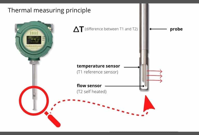
One of the sensors is heated by the circuitry and serves as the flow sensor, while a second RTD acts as a reference sensor and measures the gas temperature. The SAGE proprietary sensor drive circuitry maintains a constant overheat between the flow sensor and the reference sensor. As gas flows by the heated sensor (flow sensor), molecules of the flowing gas transport heat away from this sensor, the sensor cools, and energy is lost. The circuit equilibrium is disturbed, and the temperature difference (ΔT) between the heated and reference sensors has changed. The circuit will replace the lost energy within one second by heating the flow sensor to restore the overheat temperature.
The electrical power required to maintain this overheat represents the mass flow signal. There is no need for external temperature or pressure devices.
One of the advantages of TMFMs is that they have no moving parts, which reduces maintenance and permits their use in difficult application areas, including saturated gas. They also do not require temperature or pressure corrections and provide good overall accuracy and repeatability over a wide range of flow rates. This style of meter calculates mass flow rather than volume and is one of the few categories of meters that can measure flow in large pipes.
SAGE METERING Difference
SAGE first brought the digitally-driven circuit design to market, eliminating the traditional analog Wheatstone bridge. This feature provides SAGE products with the ability to:
- Eliminate analog drift, which improves stability and long-term reproducibility
- Show a reproducible zero flow point, permitting simple and reliable calibration verification
- Maintain higher resolution providing greater rangeability
- Eliminate self-heating because of digitally-driven temperature sensor
- Match overheat to application for greater signal resolution
- Offer a remote style up to 1000’ from the probe and lead-length compensated (since the junction box has no circuitry, it is suitable for harsh environments)
- Ensure accurate flow measurement over a wide range of process temperatures due to improved temperature compensation
SAGE has brought to market the first graphic display in the thermal flow industry, which provides the following:
- Flow rate, temperature, totalized flow, diagnostics, and signal at a single glance
- A high-contrast graphic display that adjusts to ambient lighting, making it easy to read
Calibration Requirements
Installation variances and gas composition often impact flow meter performance. Most TMFM manufacturers require periodic recalibration to assure accuracy; in that case, the meter must be taken offline and returned to the factory (or a third party). This is expensive and inconvenient.
The EPA GHG Reporting Rule requires that the meters be checked frequently for calibration. The SAGE meter offers the convenience of quickly verifying that the meter is accurate through the SAGE In-Situ Calibration. The SAGE product does not have to be removed. Calibration verification can be performed in the pipe easily and inexpensively, saving time and money from removing the meter and returning it for periodic recalibration.
All Sage Paramount and Prime meters can perform the in-situ calibration check as long as a “no flow” (0 SCFM) condition can be created. “No flow” is easily created using an isolation valve assembly with the insertion meter style. Unlike other TMFMs, the SAGE In-Situ Calibration verifies that the unit is accurate and detects that the sensor is clean. If the meter does not pass the calibration check the first time, in most cases, simply cleaning the sensor and re-testing will verify that the meter is accurate and hasn’t drifted or shifted.
When the SAGE meter is calibrated, the SAGE Zeroing Chamber records the “no flow” or 0 SCFM data point while subjecting the unit to the customer’s specified conditions (i.e., the gas or gas mix and pressure). This data point at “no flow” is one of many data points used for the flow meter’s NIST traceable calibration and is used as a convenient standard for the calibration check. This data point is conveniently recorded on the meter’s tag and the meter’s Certificate of Conformance.
Traditionally, TMFMs have relied upon the Wheatstone bridge, an electrical circuit used to measure resistance but prone to drifting. One of the unique elements of SAGE’s approach is the ability to use a hybrid digital method of driving the sensors. The proprietary technology provides additional benefits, which include: improved signal stability, enhanced temperature compensation, better sensitivity to detect flow changes, improved resolution, and the capability to adjust the meter’s operating range to match the customer’s specific operating conditions.
The EPA regulations (CFR 40 Part 98) require that the calibration of the flow meter be verified per the manufacturer’s recommendations regularly. Other TMFM manufacturers have recognized the benefit of an in-situ calibration verification, and a few manufacturers have developed their methods to verify calibration for their meters:
- One manufacturer’s verification process requires the purchase of expensive add-on hardware.
- Other manufacturers require the TMFM to be returned to the factory or a third party for recalibration. This is inconvenient and expensive, especially if the meter is used outside the manufacturer’s country, which is typical for companies measuring carbon credits.
- Another manufacturer’s process only verifies the electronics are operational and not that the meter is calibrated.
SAGE’s In-Situ Calibration verification process is straightforward, easy to perform in the pipe, and inexpensive. The process verifies that the sensor and electronics are operational, eliminates the need for a factory recalibration, and meets all EPA regulations.
GHG Emissions Monitoring Applications
Facilities emitting 25,000 metric tons of CO2e annually are required by the EPA to report annual emissions per EPA mandate 40 CFR Part 98.
TMFMs offer a reliable solution to measure, monitor and control gas mass flow for various environmental applications. Because of their low-end sensitivity, the SAGE TMFM can accurately measure extremely low velocity, down to 5 SFPM, making it highly effective for biogas, digester gas, landfill gas, and flare gas operations. When measuring gas mass flow with TMFMs, temperature or pressure compensation is not required like in many other flow measurement technologies. Because TMFMs have no moving parts, they have fewer maintenance and repair issues than other technologies.
TMFMs offer solutions for measuring and monitoring GHG emissions and projects that turn waste gas into energy.
General Stationery Fuel Combustion
Subpart C
Subpart C of 40 CFR 98 covers all aspects of general stationary fuel sources, which are mechanisms that combust fuel, usually to produce electricity, generate steam, or provide energy for industrial, commercial, or institutional use. Alternatively, they can decrease waste by removing combustible matter.
These combustion sources include boilers, furnaces, engines, simple and combined-cycle combustion turbines, process heaters, and incinerators in commercial buildings and various industries, including refineries, chemical plants, paper mills, natural gas production fields, and pipelines.
Subpart C requires reporting GHG (CO2, CH4, and N2O), which are waste products in fossil fuel combustion. One method facilities can use to report emissions from combustion sources is continuous emission monitoring (CEM). Here the facility measures the total flow rate of exhaust gas along with the individual concentrations of CO2, CH4, and N2O in the total gas flow. This method is costly and requires ongoing maintenance.
To simplify reporting, the EPA permits the facility to measure fuel consumption over a year and then apply EPA formulas that calculate the emissions of various GHGs. The formulas are found in 40 CFR 98 Subpart C. A facility fueled by natural gas or biogas can easily measure (totalize) the fuel used with a flow meter and apply the EPA formulas. Since the EPA has different factors for each type of fuel, a facility using different fuels will need to totalize the consumption of each fuel type.
The SAGE meter is easy to install and directly measures mass flow. A built-in totalizer also provides the total flow in SCF (or NCM). The SAGE meter has an extremely low-end sensitivity which is needed in this application. It can be verified onsite through the easy in-situ calibration check without removing the meter from the pipe, fully complying with the EPA flow measurement standards.
Industrial Wastewater Treatment
(Subpart II)
Subpart II covers methane emissions from industrial wastewater treatment facilities, including ethanol production and food processing.
Biogas
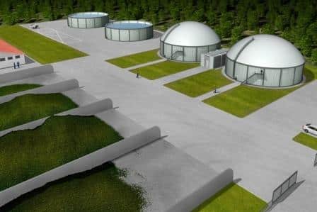
Methane (CH4) in the form of biogas naturally occurs from the decomposition of organic material in the absence of oxygen. This typically occurs in an anaerobic reactor or anaerobic lagoon. Biogas typically contains approximately 65% CH4 and 35% CO2 and traces of other gases.
In the wastewater process, digesters break down the waste material creating digester gas, a mixture of methane and carbon dioxide. Digester gas can be converted to renewable energy to fuel onsite boilers and flare the excess. Other systems can use the gas to generate electricity, sell the energy to local industries or even create fuel for natural gas-fueled vehicles.
Anaerobic digester gas is dirty, wet (saturated), and contains contaminants that can collect within the piping. A TMFM has no moving parts making it an optimum choice for this application. Most wastewater digester gas applications function at low pressure, and TMFMs have no pressure drop. The SAGE Meter has an extremely low-end sensitivity which is needed to handle the very low flow typical of digester gas. Throughout this process, TMFMs are used to optimize the process and comply with EPA regulations.
Manure Management
(Subpart JJ)
Subpart JJ covers all aspects of the manure management system, which stabilizes or stores livestock manure in at least one of the following: uncovered anaerobic lagoons; liquid/slurry systems with and without crust cover (including but not limited to ponds and tanks); storage pits; digesters, including covered anaerobic lagoons; solid manure storage, drylots, including feedlots; high-rise houses for poultry production (poultry without litter); poultry production with litter; deep bedding systems for cattle and swine; manure composting.
Biogas
Biogas is produced from organic matter. It can be derived from a fermentation or anaerobic digestion process from organic feedstock, such as manure, sewage, agricultural waste, municipal waste, biomass, and some industrial waste from food and beverage manufacturers. Biogas is a blend of approximately 65% CH4 and 35% CO2. Methane traps heat in the atmosphere over 20 times more than carbon dioxide and remains in the atmosphere for nine to fifteen years.
The biogas can be used to create energy while simultaneously reducing GHG emissions to improve the environment. Among the industries producing methane include farming operations and landfills.
Farming Operations
 Digester gas from farming and other agricultural operations is generated from the breakdown of livestock waste when the gas is captured within a large plastic cover, known as a digester. The manure decomposes in the absence of oxygen (anaerobic digestion). Normally the decomposition of livestock waste results in vast amounts of methane which vents naturally into the atmosphere.
The digester creates biogas, a mixture of approximately 65% CH4 and 35% CO2. This gas can then be captured and destroyed in a process called methane destruction, which is accomplished by burning the gas in a flare or an engine. While the process creates carbon dioxide (a GHG), methane destruction is a very responsible method to reduce GHG emissions since methane is 21 times more potent than carbon dioxide.
In addition, methane destruction can also provide a source of fuel for heating or generating electricity.
Hundreds of farming operations reduce GHG emissions, accrue emissions credits to meet EPA’s reporting standards, and create renewable energy.
TMFMs can quantify the emissions saved by measuring the mass flow rate. Since the environment is challenging and there are varying flow rates, many other flow technologies are unsuitable. The SAGE meter has a rangeability of at least 100:1 and as high as 1000:1, making it extremely accurate over a wide flow range which is needed because of gas spikes and seasonal climate changes. The SAGE sensors are clad in a protective 316 SS sheath and protect against corrosion.
The SAGE meter excels in these applications:
- They have low-end sensitivity making them accurate at very low flows.
- The easy in-situ calibration verification procedure complies with the EPA’s requirement for periodic calibration checks.
Municipal Solid Waste Landfills
(Subpart HH) and
Industrial Waste Landfills
(Subpart TT)
Subpart HH covers all aspects of municipal solid waste landfills, while Subpart TT covers industrial waste landfills. Flow meters can measure landfill gas and determine methane emissions in both subparts.
Landfill Gas Monitoring
Landfill gas (LFG) is a biogas derived from municipal solid waste. Its composition can vary, yet it generally contains more carbon dioxide and less methane than digester gas. The composition is closer to half and half. In some landfills, gases are extracted from multiple wellheads and collected through a network of pipes leading to a common header pipe. Some landfill facilities use LFG to generate renewable energy (LFGTE). These facilities create energy to heat onsite buildings, boilers, and kilns, run generators to create electricity, and even produce liquid or liquefied natural gas (LNG) for vehicles.
Aside from generating energy from waste, landfills frequently participate in carbon offset projects through methane destruction. Landfill gas is collected and destroyed at over 1000 landfills worldwide, which reduces GHG emissions and accrues carbon credits.
In facilities where LFG is not used to create renewable energy, the EPA requires that the gas be collected and flared into the atmosphere to prevent its release.
Accurate flow measurement is required to quantify saved emissions for landfill gas monitoring and reporting. Whether the gas is extracted from wellheads, recovered in LFGTE applications, collected for carbon offset projects, or flared to prevent its release, TMFMs offer accurate and repeatable measurements.
TMFMs meet the challenges of the environment, which include varying gas compositions, wet (saturated) and dirty gas, a potentially explosive environment, and fluctuations in gas flow, including extremely low flow. The calibration of the SAGE meter can be verified onsite through the easy in-situ calibration check without removing the meter from the pipe, complying with the EPA flow measurement standards.
Petroleum and Natural Gas Systems
(Subpart W)
Subpart W covers all aspects of the natural gas industry, including offshore production, onshore production, processing, transmission, underground storage, liquefied natural gas (LNG) storage, LNG import and export, and natural gas distribution.
Several applications range from high flows for the blown-down vent stack to the very low flow rates found in compressor seal leakage. Many of the emission sources are from venting and fugitive emissions. The EPA estimates that fugitive and vented GHG emissions in petroleum and natural gas facilities are the second largest source of human-made methane emissions in the United States.
While some GHG sources can be estimated or modeled, the large number of different sources makes calculating GHG emissions very complex. Over the long term, direct measurement of GHG emissions will be simpler, requiring much less time and workforce than performing all the necessary calculations. In addition, obtaining exact measurements of the natural gas leakage loss will provide the operator with valuable information to help improve the performance of their operations.
SAGE TMFMs are ideally suited for direct measurement of GHG emissions. The very low flow rates in small pipe sizes can easily be measured using SAGE’s flow body designs which range from ¼ inch to four inches. The higher flows in the larger pipe sizes can easily be handled with the insertion probe. The high turndown capabilities and the excellent resolution provide the most accurate flow measurements over a broad range of flow rates. Particularly important is the in-situ calibration verification, which permits the user to verify that the operating performance of the SAGE insertion TMFM meets the performance when the unit was initially calibrated. The ability to perform this test without removing the flow meter from the pipe is of utmost importance to the user.
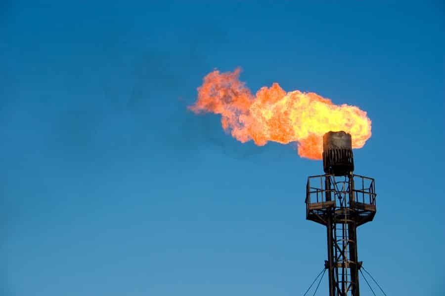
Flare Gas Monitoring
There are many operations or applications where waste gas is flared into the atmosphere. Flare stacks are typically seen at oil and gas wells, refineries, drilling rigs, natural gas plants, wastewater treatment plants, chemical plants, and landfills. Strict regulations, like the Mandatory Reporting of Greenhouse Gases Rule (40 CFR 98), require operations to measure and record the consumption of flare gas.
EPA 40 CFR part 98 requires reporting by 41 industrial categories. The categories are divided into subparts. Since flaring gas is common in many industries, the following subparts apply:
Subpart Q – Iron and Steel Production
- Flaring blast furnace gas and coke oven gas
Subpart Y – Petroleum Refineries
- Flaring waste gas
Subpart W – Petroleum and Natural Gas Systems
- Flaring natural gas
- Flaring various gases created during the processing of natural gas
Subpart X – Petrochemical Production
-
Strict regulations, like the Mandatory Reporting of Greenhouse Gases Rule, require operations to measure and record the consumption of flare gas. Flaring various gases during petrochemical production
Subpart II – Industrial Wastewater Treatment
- Flaring biogas (rather than using it for fuel at a combustion source)
Subpart JJ – Manure Management
- Flaring biogas (rather than using it for fuel at a combustion source)
Subpart HH – Municipal Solid Waste Landfills
- Flaring LFG at a municipal landfill
Subpart TT – Industrial Waste Landfills
- Flaring LFG at an industrial waste landfill
Measuring flare gas becomes a challenge for most flow meters. Ultrasonic flow meters are an effective tool for measuring flare gas. They tolerate some condensed liquid, are not affected by gas composition, and endure fluctuations in pressure and temperature. With this type of performance, however, come high costs ranging from $50,000-$100,000 per installation.
When flaring applications of known gas composition exist and water vapor isn’t condensing, TMFMs make an attractive alternative for flare gas metering. The SAGE meter has a wide turndown of up to 1000:1 rangeability, which means it accommodates extreme flow conditions and large flow swings. Under typical venting situations, low velocities are associated with flare gas, yet high velocities are typical in upset conditions. Additionally, their fast response to flow changes, low-pressure loss, accuracy (1% of reading plus 0.5% of full scale over a 100 to 1 turndown), and reproducibility make the meter a contender in flare applications.
Companies are taking advantage of the cost savings associated with TMFM, which are $5000 or less, versus the $50K to $100K for an ultrasonic application. Operations realize that by identifying the gas at the flare application, SAGE can adjust the meter to measure the known flare gas. This works for applications where compositional changes are known or are seasonal. While a bit more inconvenient than an ultrasonic meter, in many cases, the savings warrant minor difficulty.
It is clear that while TMFMs are not the perfect choice to measure flare gas, however, in many flare applications, the meter makes good sense; specifically where the composition is known and where there is no condensation. Such applications include natural gas flare at on-onshore off-short facilities. In applications with known variations in gas composition, SAGE can estimate variations in accuracy based on gas composition analysis.
SAGE Insertion Style TMFMs provide the wide turndown required to cover both the extremely low flows (low velocities) associated with normal venting and the extremely high flow (high velocities) associated with an upset condition. Their fast response to flow changes, low-pressure drop, and reproducibility are important for a flare application. In addition, SAGE products provide the customer with a unique in-situ calibration check at a “no flow” (0 SCFM) condition. This vital procedure assures that the meter has retained the original NIST Traceable calibration, verifies the meter’s accuracy, confirms that the sensors are clean, and that the flow meter hasn’t drifted or shifted. This is a tremendous benefit since it eliminates the cost and inconvenience of annual calibrations on the flow meter and provides the data needed to comply with several environmental protocols.
Other Noteworthy Subparts
There are other subparts to EPA 40 CFR 98 that are worthy of note:
Underground Coal Mines
(Subpart FF)
Active and under-development underground coal mines are required to sample mine ventilation and degasification systems. The flow rate and methane concentration from each ventilation well or shaft must be measured. A continuous flow meter can be used, or the flow rate can be periodically sampled quarterly.
Petrochemical Production
(Subpart X)
Facilities producing various petrochemicals must report GHG emissions, specifically CO2, CH4, and N2O, from petrochemical units not associated with combustion sources which would be reported under Subpart C.
Petroleum Refineries
(Subpart Y)
Petroleum refineries produce gasoline, gasoline blending stocks, naphtha, kerosene, distillate fuel oils, residual fuel oils, lubricants, or asphalt (bitumen) by the distillation of petroleum or the re-distillation, cracking, or reforming of unfinished petroleum derivatives. These facilities must calculate and report CO2, CH4, and N2O from various refinery processes.
These facilities must also report under Subpart MM – Suppliers of Petroleum Products.
Geologic Sequestration of CO2
(Subpart RR)
Facilities that inject CO2 underground for geologic sequestration must report the amount of CO2 sequestered. Geologic sequestration is a process of injecting CO2 into deep subsurface rock formations for long-term storage. This is more commonly known as carbon capture and storage (CCS).
Injection of Carbon Dioxide
(Subpart UU)
Facilities that inject CO2 underground for improved oil and gas recovery must report CO2 received for injection.
Summary
With EPA now requiring emitters to report annual GHG emissions, flow meters are being scrutinized to find the best ways to measure and report data. TMFMs are becoming the preferred choice to monitor and measure GHG emissions in biogas, digester, landfill, and flare gas applications. One of the primary advantages TMFM has over volumetric meters is that the meter measures mass flow. The SAGE products are state-of-the-art as the manufacturer is the first to bring a digitally driven sensor, a graphic display, and onsite calibration verification to market. The SAGE meter is the only TMFM that provides a convenient, in-situ, and in-line calibration check that assures the flow meter retains the original NIST traceable calibration and is accurate.