 Skip to content

Sage Metering is happy to announce the release of our eBook “An Industry Guide for the Use of Thermal Mass Flow Meters: Oil & Gas Production, Waste Management, Steel.” The book is by Bob Steinberg, President of Sage Metering.

Introduction
The thermal mass flow meter measures the total mass flow rate through a pipe determined from convective heat transfer. Mass flow rate, rather than volumetric flow rate, is sought in most industrial applications, and thermal mass flow meters have the advantage of monitoring mass flow rate directly. Thermal mass flow meters optimize efficiency, save money, improve product quality, decrease harmful emissions, maintain system balance, combustion optimization, or provide leak detection.
Standard applications for this meter type include combustion air, preheated air, drying air, aeration, and digester gas, fuel gas, natural gas distribution (non-custody transfer), stack gas, flare gas, HVAC, occupational safety, and health monitoring; environmental, natural convection, and fermentors.
This eBook outlines some of the thermal mass flow meter applications in the oil and gas industry, waste management, and steel industries. It also provides an overview of uses in automobile manufacturing, chemical and petrochemical, food and beverage, industrial compressed air, and pharma and biotech industries.
Oil and Gas Production, Waste Management and Steel Applications
Review the book here in our flipbook or download the PDF for FREE.
Principle of Operation
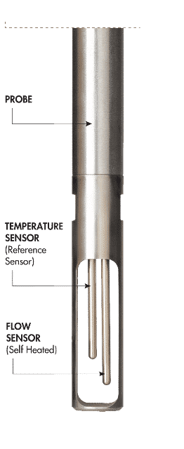
There are insertion and inline (also called “in-line”) thermal mass flow meters, and in either case, the probe of the meter supports two sensors that extend into the gas flow. The Sage Metering sensors are resistance temperature detectors (RTDs), consisting of durable reference-grade platinum windings protected in a 316 stainless steel sheath.
During the thermal mass flow meter operation, a circuit heats the flow sensor while a second detector acts as the reference sensor to measure the gas temperature. As gas flows past the heated sensor, gas molecules carry heat away from the heated sensor. The circuitry maintains a constant overheat between the flow and the reference sensor. A change in the mass (molecular) flow rate changes the amount of cooling, resulting in a temperature change, disrupting the circuit balance. Almost instantly, the circuit reestablishes the lost energy by varying the power to the flow-sensor to obtain the correct overheat temperature. The electrical power used to maintain this overheat determines the mass flow signal.
For the insertion-style flow meter, the sensors insert through a sealed compression fitting and isolation valve assembly or flanged mounting in a pipe, duct wall, or similar flow channel. For the inline meter, the sensor probe that supports both sensors is installed permanently into a pipe (with built-in flow conditioners) with flanged or threaded connections (or tube).
To read more, download the PDF for FREE.