

In part one of this five-part series, we explore stoichiometric combustion—the theoretical concept in which the optimal ratio of oxygen to fuel produces the maximum heat output while achieving the highest possible combustion efficiency for industrial boilers.
Industry Impact: The Numbers That Matter
According to U.S. Department of Energy data, optimizing combustion efficiency can reduce industrial fuel consumption by 5–20%, with some facilities achieving even greater gains when precision monitoring systems are combined with equipment upgrades. With natural gas prices fluctuating between $2 and $8 per million British thermal units (MMBtu) in 2024–2025, the financial stakes for efficient combustion are substantial.
Key Statistics:
- Industrial boilers consume roughly 4.6 quadrillion British thermal units (Btu) annually in the U.S.
- Poor combustion control results in an estimated $2.3 billion in annual fuel costs (based on DOE waste factor estimates).
- Facilities using advanced combustion monitoring often report efficiency improvements of 8–25% in case studies.
Combustion Efficiency
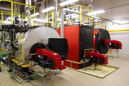
A significant way to reduce energy consumption in a manufacturing environment is to optimize the combustion control on industrial boilers, steam generators, furnaces, ovens, smelters, and process heaters. We achieve combustion efficiency and energy management through accurate and repeatable measurements of gases.
Combustion Control
By monitoring the air and fuel rates to burners, optimal ratios are achieved, resulting in significant reductions in fuel gas cost, improved process efficiency, enhanced product quality, and better yields while simultaneously lowering combustibles. Many local and statewide jurisdictions have environmental regulations requiring flow meters on medium and large-sized heating units to measure plant-wide emissions. Typical applications for combustion control monitoring are found in various industries, including textile, glass manufacturing, automotive, aluminum & steel, food & beverage, pulp & paper, power, chemical, and refining.
Modern Combustion Monitoring Technology
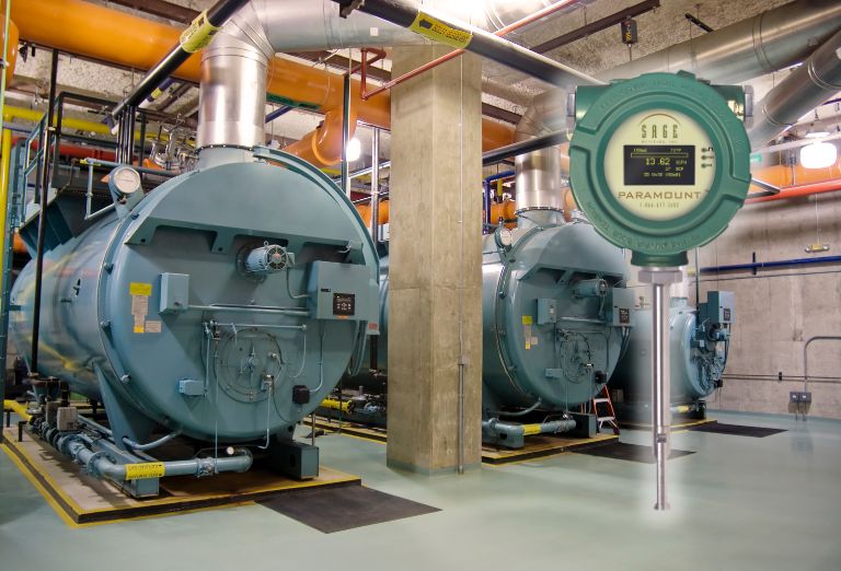
Today’s industrial facilities use advanced thermal mass flow meters to operate closer to stoichiometric conditions than ever before. The Sage Paramount thermal mass flow meter, for example, offers:
- Air and fuel flow measurement with ±1% accuracy under standard calibration conditions
- Rapid response to combustion changes in seconds
- Ability to maintain stable air-fuel ratios across varying load conditions
- Data logging to document efficiency improvements for compliance and reporting
Achieving this precision was challenging with older measurement methods. Modern thermal mass flow meters now make stoichiometric combustion far more practical in real-world operations.
Efficiency Results May Vary
Reported savings are based on typical DOE findings and industry case studies. Actual results depend on your facility’s equipment, fuel quality, operating practices, and maintenance. Advanced thermal mass flow meters can help optimize combustion control, but no technology can guarantee a specific percentage of improvement under all conditions.
Stoichiometric Combustion
The purpose of combustion is to efficiently consume fuel and produce heat. There are three components of combustion: fuel, oxygen, and heat. The most common fuel sources in the combustion process are fossil fuels, natural gas, oil, and coal. Fossil fuels are hydrocarbons, organic compounds containing carbon and hydrogen. To maximize combustion efficiency, it is vital to consume (or burn) all the fuel, which is known as complete combustion.
It is essential to introduce air into the combustion chamber to achieve complete combustion. Without it, the fuel will have limited or incomplete combustion, and the exhaust gases will include some unburnt and partially burnt fuel. Assuming we are evaluating a natural gas-fed combustion process, the unburnt fuel components will be carbon monoxide (CO), hydrogen (H2), as well as methane (CH4).
Combustion efficiency depends on using the right amount of air to consume the fuel.
Fuel Consumption
The presence of uncombusted or partially burned fuel indicates incomplete combustion, which significantly reduces efficiency. Therefore, burning the fuel in excess oxygen ensures that the fuel will achieve complete combustion.
Excess Oxygen
All excess air heats in the combustion chamber during the combustion process, and this energy is lost in the exhaust. For this reason, the next governing factor of combustion control is to minimize the extra oxygen used to reduce the loss of energy from heat going up the stack.
Stoichiometric combustion is a theoretical position where the optimal amount of oxygen and fuel mix generates the most heat possible, achieving maximum combustion efficiency. There are no unburnt combustibles and no excess air. It is something to strive for, though, in reality, it does not exist. It is theoretical, and in an actual combustion process, the mixing between the air and fuel does not support the best conversion.
Environmental and Regulatory Benefits
Operating near stoichiometric combustion can deliver significant environmental advantages:
Emissions Reduction:
- Lower NOx formation by minimizing excess air while avoiding incomplete combustion
- Lower CO₂ emissions per unit of energy output due to improved fuel efficiency
- Reduced unburned hydrocarbons and other minor combustion byproducts (particulate matter reductions are most relevant for solid fuels)
Regulatory Compliance:
Many facilities are required to report greenhouse gas emissions under EPA 40 CFR Part 98. Stable, optimized combustion can help facilities:
- Maintain consistent, verifiable emissions data
- Enable accurate measurement and documentation of combustion efficiency improvements
- Demonstrate environmental stewardship to regulators and stakeholders
- Potentially meet criteria for carbon-reduction incentives or credits where available
Frequently Asked Questions
What is the difference between stoichiometric and complete combustion?
Stoichiometric combustion is the theoretical perfect air-fuel balance, with no excess air or unburned fuel. Complete combustion means all fuel is burned, but there may still be excess air, which can lower efficiency.
Can stoichiometric combustion actually be achieved in practice?
True stoichiometric combustion remains theoretical due to real-world mixing limitations. However, modern thermal mass flow meters enable operation within 2–5% excess air, which is very close to the ideal.
How much can proper combustion control save on fuel costs?
Many facilities report 8–25% reductions in fuel consumption when implementing precision control, though actual savings vary.
Which industries benefit most from stoichiometric combustion optimization?
Energy-intensive industries such as steel, aluminum, glass, petrochemicals, and large institutions with significant heating loads see the greatest benefits.
In part two of this series, we will explore the balance of using excess air to consume combustibles while reducing energy loss up the stack.
Air Flow Meter for Combustion Efficiency | Industrial Boilers