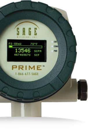
In part one of this blog series on flowmeter analog wiring communications, I answer a frequently asked question. “How do I wire an internally powered Sage thermal mass flow meter with a 4-20mA output?”
How to wire an internally powered Sage flow meter with a 4-20mA output?
In the following video, I show the wiring configuration for the DC powered Sage Prime with a 4-20mA output. For decades, the 4-20mA signal is one of the most common mediums for signal transmission and electronic control in commercial and industrial environments.
There are three vertical lines of terminals identified as A, B, and C terminals (from left to right) on the rear of the Sage meter. Each of these vertical lines has six terminals, the top being #1 and bottom being #6 with the centers designated by consecutive numbers (2-5).
- Hook up the DC power to the meter. It is accomplished by identifying the “B” terminals (the center), then connect the negative wire (black) to the B6 terminal and the positive wire (white) to the B5 terminal.
- Note that a jumper is required between the B4 – B5 for the internal 4-20mA signal to work correctly.
- Connect the 4-20 mA wires. Connect the ground wire (generally black) to terminal C6 and the return wire (usually red) to C5.
Flow Meter Wiring Video
I connect a multimeter and power up the meter in the video, demonstrating how the 4-20mA device should read around 4mA at 0 flow (as long as the flow is off).
I will soon review other wiring configurations available for pulsed, 4-20mA, and Modbus outputs and communications.
As always, our Customer Service Department is available to assist you. If you have questions, please call us.
FAQ – How to wire Sage thermal mass flowmeter with pulsed output?

