 Skip to content

Here are the in-situ gas flowmeter calibration directions. The Sage method to verify that the thermal mass meter is still in calibration allows the meter to remain in the pipe, is easy and quick, and checks both the sensor and transmitter’s performance. To compare the Sage method to other manufacturers’ onsite calibration methods, visit “Thermal Mass Flow Meter Manufacturers’ In-Situ Calibration Methods.”
Sage In-Situ Calibration Verification
The Sage Prime and Sage Paramount continuously show the raw calibration milliwatts (mW) on the top left-hand corner of the meter’s display. To conduct an “in-situ” calibration check quickly and conveniently, one simply compares the raw mW data with the initially reported “no flow” value. The initial data is on the data tag on the back of the meter (as well as on the Certificate of Conformance). If they match, it verifies that the meter is in calibration and confirms that the sensor and transmitter are accurate, that there is no drift or shift, and that the sensor is clean.
Calibration Directions
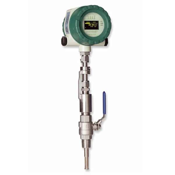
Create and verify that there is no gas flow. Users can perform the onsite calibration procedure whenever they create a “no flow” condition. The user can accomplish this in a few ways. The obvious way is to close off the process gas flow. However, this is not always easy or possible, particularly in natural gas supply lines. Another inexpensive way to create a no-flow condition is to use one of the Sage Isolation Valve Assemblies (P/N SVA05 or SVA07). These assemblies are an affordable add-on for the Sage meter.
-
- Loosen the valve assembly’s lower collar clamp thoroughly using an Allen wrench (for the SVA05, use 9⁄64”, and for the SVA07, 3⁄16”), and slightly loosen its compression filling until the probe can easily lift.
- Raise the meter’s probe until the safety chain becomes taut, tighten the compression fitting, and then close the valve shut off with its handle. Doing so removes the meter probe from the pipe and creates a “no flow” condition.
- Check the meter display’s milliwatt (mW) reading and compare it to the flow meter mW value on the tag (or Certificate of Conformance). If they match, the unit calibration check is complete.
Alternatively, the user can perform an ambient air test to create a “no-flow” condition. In this case, merely remove the pipe’s probe and cover the sensor with a plastic bag. Then place the capped probe into an empty plastic water bottle.
Compare the raw data mW display with the initial factory data. Note the raw mW number on the top left-hand side of the meter’s display. After one to three minutes of “no flow,” check the reading against the flow meter’s data tag on the back of the meter. This data is also on the last line(s) of the meter’s Certificate of Conformance.
A value within five milliwatts (mW) of the original factory value (assuming the user checks the same gas at the same pressure) indicates that the meter is still in calibration.
A value between 5-10 mW of the initial factory value also means that the meter is still in calibration, but the reading may have been influenced by one or more of the following factors:
-
- gas composition
- pressure
- dirt
- non-zero conditions
- sensor orientation
If we investigate and correct these factors, one should expect that the difference between the “no-flow” mW display and the initial factory data would be less than or equal to 5 mW.
If the meter fails (or is borderline) the calibration verification, it is more likely that the sensor is dirty, and the next step would be to clean the sensor. A contaminated sensor could create additional heat transfer. One of the advantages of the Sage in-situ analysis is that it will not pass the calibration. In this case, remove the probe and clean the sensor (use a non-corrosive solvent). A soft brush may gently clean the sensor surface; however, use caution and avoid damaging the sensor elements (RTDs).
In any case, a technician in the field may be unable to simulate the initial Sage calibration conditions entirely while in the pipe. For this reason, a difference of 10 mW is acceptable and indicates the meter is still in calibration.
Why do we need In-Situ Calibration?
The Sage onsite calibration verification is a simple procedure that eliminates the need for annual factory calibrations and offers tremendous benefits to the user. This verification, of course, saves time and money for the user. Sage Metering recommends a quarterly in-situ calibration check for EPA 40CFR 98 and CDM Methodologies to comply with some greenhouse gas or climate change regulations.
For CAR compliance, Sage Metering recommends a quarterly In-Situ Calibration Check for the following Protocols:
- U.S. Landfill Protocol, Version 4.0, Par. 6.2
- U.S. Livestock Protocol, Version 3.0, Par. 6.2
- U.S. Livestock Protocol, Version 4.0, Par. 6.3
- Mexico Landfill Protocol, Version 1.1, Par. 6.2
- Mexico Livestock Protocol, Version 2.0, Par. 6.2
As per the protocols, the maximum allowable drift is 5%. Calculate the drift by multiplying the mW change from the factory value (see 2) by 1.0% (i.e., each mW change equals 1% drift).