 Skip to content

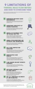
The thermal mass flow meter is a widely accepted instrument that measures gas mass flow. The device is used in various industries, including oil and gas, refining, chemical, mining, and wastewater. The meter is accurate, reliable, and cost-effective for many applications. However, like any technology, the flow meter’s limitations may present challenges the user should address before implementation. Here are nine restraints or challenges of thermal mass flow meters and how to overcome them.
1. Condensed Moisture may Cause Inaccuracies

The primary thermal mass flow measurement principle involves heat transfer caused by the gas flow. Condensed moisture in the gas that contacts the heated sensor rapidly increases heat transfer, and the instrument responds with a spike, creating inaccurate flow measurement.
How to overcome this challenge:
-
- When gas flows into a vessel, such as a knockout drum (KO drum or knockout pot), there is a reduction in gas velocity and a change in the flow direction. The gas flows upward and out, effectively removing moisture drops from the gas as gravity causes the moisture to fall.
- Angling the flow sensor in the pipe is another method that can mitigate inaccuracies associated with condensed moisture. Angle the sensor so that if condensate develops, it flows away from the sensor.
2. Diminished Sensitivity at Higher Velocities
There is a nonlinear relationship between the mass velocity and heat transfer in thermal flow measurement. While thermal flow meters provide excellent sensitivity for low gas flow, there is diminished sensitivity at high rates. When selecting a mass flow meter for a given application, the meter is sized based on mass velocity referenced to the STP (Standard Temperature and Pressure) conditions. Other flow meter types are sized based on the velocity at operating conditions.

As gas pressure increases, the gas molecules pack closer together, increasing gas density. The mass velocity measured by thermal mass flow meters increases with increasing gas density while the actual velocity at operating conditions remains the same.
How to overcome this challenge:
Because the thermal meter loses sensitivity at higher mass velocities, there is an upper limit on velocity, and the instrument can overrange. For this reason, it is uncommon to use thermal mass flow meters in compressed gas systems with pressures greater than 150 PSI. In these cases, vortex-shedding or differential-pressure flow measurement are options.
3. When Unable to Calibrate with the Actual Gas Type
Every gas has different physical properties that impact heat transfer. For this reason, a thermal mass flow meter can only accurately measure the gas (or gas mixture) the meter was calibrated for. A controlled amount of the specified gas flows past the meter’s sensor during calibration on a flow bench, and the signal is measured. This process is repeated multiple times over the operating range to establish the relationship between mass flow and the signal for the gas and sensor being calibrated.
How to overcome this challenge:
When safety or hazardous conditions make it impossible to use the actual gas (or gas mixture) during calibration, use a surrogate gas with similar heat transfer characteristics combined with analytical adjustments based on the relative heat transfer properties of the actual and calibration gases.

4. Annual Recalibrations are Expensive and Inconvenient
Once a thermal mass flow meter has been calibrated, the question becomes, when does it need to be re-calibrated? Some manufacturers require their meters returned to the factory or an authorized NIST-traceable facility for recalibration. This recalibration can be expensive, and removing a meter from service is certainly inconvenient. With technological advancements over the years, some mass flow meter manufacturers, including Sage Metering, have developed ways to verify that the meter remains calibrated. These calibration verification procedures vary from manufacturer to manufacturer. While some methods are straightforward, others are complicated, time-consuming, and require the meter to be removed from the pipe.
How to overcome this challenge:
In the in-situ method of one manufacturer’s verification process (Sage Metering), the user may verify the meter is in calibration by comparing one data point with the original calibration data. A retraction assembly with a compression seal and ball valve permits the user to withdraw the sensor from the pipe, creating a no-flow condition even though the gas line is still in service. It is then possible to compare the zero flow signals during the test and calibration, and if they match, this comparison verifies that the meter remains in calibration.
5. Gas Flow Composition Variation
Given that a thermal mass flowmeter requires calibration for the gas being measured, any change in the gas composition will produce incorrect data (see challenge #3 regarding the calibration). Of course, the degree of inaccuracy will depend on the gas variation.
How to overcome this challenge:
Biogas is a mixture of varying amounts of methane and carbon dioxide. In most cases, the change in heat transfer from the gas difference impacts the overall accuracy by less than 5 percent. In many circumstances, this is considered acceptable. However, there can be substantial variation in composition in other applications, such as flare gas at a refinery or chemical plant, which significantly impacts the meter’s accuracy. Knowing the gas composition allows some manufacturers to develop correction factors for the new gas.
6. Undeveloped Flow Profile
During the calibration of the thermal mass flowmeter, the test station provides a fully developed turbulent flow profile at the sensor. Duplicating this flow profile in the field will give the most accurate results, while deviations from the recommended distance create inaccuracies. Most flow technologies require a minimum of upstream and downstream straight runs, and generally, there is more emphasis on the upstream range. The recommended straight run to create the ideal flow profile is often unavailable at the site. As a guideline, a space of 15-25 pipe diameters downstream of a single elbow is typically sufficient.
How to overcome this challenge:
-
- Sometimes, the client chooses to use the flow meter with the undeveloped profile and sacrifice some accuracy, knowing the data will be highly repeatable.
- Alternatively, a flow conditioner assembly can assist when a short straight run is an issue. Flow conditioners provide a uniform flow profile at the sensor location. This uniform flow profile is different from the fully developed flow profile, which occurs with an adequate good straight run. For this reason, it is necessary to calibrate the flow meter with the flow conditioner when using such a device to provide a uniform flow profile.
7. Flow Sensor Buildup Decreases Accuracy
The meter’s accuracy decreases whenever there is a buildup on a flow meter sensor. Any buildup on the flow sensor of a thermal flow meter will reduce the heat transfer and cause the meter to read lower than expected. Additionally, the built-up material increases the thermal mass and decreases the response time to changes in gas flow rate.
How to overcome this challenge:
If the thermal mass flow meter includes a retractable element consisting of a compression seal and ball valve, the meter’s insertion probe can easily be removed from the pipe and cleaned without disrupting service.

8. Obtaining Accurate Flow in Large Ducts
There is an accurate flow measurement when the recommended straight-run distance is available. The thermal mass flow meter probe is inserted into a pipe, and the meter measures the gas flow at the sensor location. Since the desired straight run is predicated on the pipe diameter, obtaining the recommended distances for large duct runs can be challenging, making it difficult to measure accurately.
How to overcome this challenge:
Improve overall accuracy by increasing the number of measurement points. In these cases, using multiple flow meters at different locations across the duct and averaging the flow measurements improves accuracy.
9. Calibrating at Low Velocities
Thermal mass flowmeters excel in low-velocity measurements. Of course, accurate measurement depends on having the meter calibrated at low velocities. Not all thermal mass flow meter manufacturers can calibrate instruments at very low flow rates.
How to overcome this challenge:
If you have a low-velocity application, always contact the manufacturer you are considering to ensure they can correctly calibrate the meter over the specified velocity range.
Parting Thoughts
Every flow measurement technology has limits. When pushing the boundaries of a thermal mass flowmeter, challenges may arise. In all situations, the best way to overcome challenges is to convey the application and operating environment details to the manufacturer so the solution provider can ensure the technology under consideration can deliver the desired results.
Reference:
“9 limitations of thermal mass flowmeters (and how to overcome them),” by Wayne Shannon