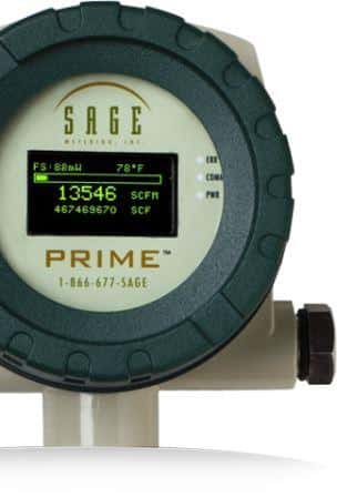
In addition to the insertion-style flow meters, Sage offers inline or in-line thermal mass flow meters in ¼” through 4”, and here are some installation considerations.
In-line Flowmeters

Sage Metering offers inline flow meter mounting styles for 1/4″ through 4″ pipe (threaded male NPT ends are standard up to 2-1/2” and ANSI 150 lb. flanged ends are recommended for the 3” and 4” models). If other mounting styles are required, contact Sage. For pipe sizes greater than 4” use the insertion-style flow meter.
The assembly section of the inline flow meter should match the size and pipe material of the conduit. The meter is plumbed directly in the flow line by threading, flanging, or welding. The user should not apply reducers with an inline flow meter. The meter has a sensing element (a self-heated flow sensor and a temperature/reference sensor) mounted in the flow section where gas will flow. The meter also contains a sensor drive circuit, microprocessor meter board, and transmitter enclosure.

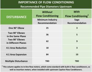
All Sage inline flow meters, 1/2″ and up, have built-in flow conditioners. The ¼” and 3/8” models do not have flow conditioners. For this reason, the inline flow meter of these sizes will require an additional straight run. Refer to the chart here for upstream straight run requirements.
Image by Peggy und Marco Lachmann-Anke from Pixabay
Other topics from the Sage Prime Manual you many be interested in are:
How to Install and Mount my Sage Prime Thermal Mass Flow Meter?
Flow Profile and Installation Considerations for Insertion Flow Meters
Correction Factors for Biogas Variation From Original Calibration

