

It may not be convenient to turn off the process-gas to perform the in-situ calibration verification procedure. The optional Sage SVA05 or SVA07 Isolation Valve Assemblies permit the user to check “no-flow” without shutting the gas supply.
Installation Considerations for Insertion Flow Meters

Although easier to install than an inline flow meter, an insertion flow meter requires proper installation and a well-developed flow profile to perform correctly. Sage offers a couple of mounting hardware sets that provide tremendous benefits to the thermal mass flow meter.
Sage Valve Assembly Operation
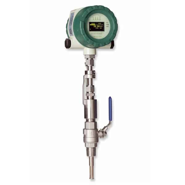
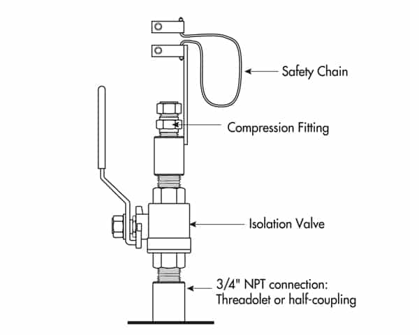
Sage Metering offers valve assemblies (PNs SVA05 and SVA05LP) as optional mounting hardware sets for the insertion-style flow meters. The hardware permits the meter user to service, clean, verify calibration, or relocate the meter without disrupting or “shut- down” the process. The probe insertion depth is adjustable, which permits the sensor to be situated at the center of the pipe, optimizing meter accuracy. The ball valve seals off process gas leaks at the insertion point when the probe assembly removes. The assembly includes a valve, threadolet, and compression fitting with Teflon ferrule, a cable restraint, and two collar clamps.
A threaded half coupling (3/4″ FNPT) correctly sized to accommodate the isolation valve retractor assembly must be fitted to the pipe or duct to which the insertion probe will be inserted. Avoid T-Fittings since they disturb the flow profile and reduce the measurement area. You may require to direct the threading together (or with necessary bushings) of the retractor assembly. In other cases, weld the threadolet in place, and drill a clearance hole through the pipe/duct to accept the probe assembly. The user may require a hot-tap drill if the pipe or duct is under pressure during installation.
Compression Fitting Operation
 A bored through tube fitting, correctly sized to accommodate an insertion probe’s specific OD, can be purchased as an option from Sage Metering or provided by the user (download Valve assemblies). Before installation, drill a clearance hole in the pipe or duct to accommodate the insertion probe assembly. A fitting (1/2″ FNPT) is then welded in place or threaded into the half-threadolet, which has been welded to the pipe or duct. The probe insertion depth is adjustable to permit the sensor to be located at the center, optimizing measurement accuracy.
Installation Instructions
-
- Insert tubing into the tube fitting.
- Make sure that the tubing is positioned correctly per the user manual pages 14 & 15.
- Due to the deviations of tubing diameters, a common starting point is desirable. Therefore, tighten the nut until the tubing will not turn by hand or move axially in the fitting.
- Mark the nut at the 6 o’clock position.
- While holding fitting body steady, tighten the nut 1-1⁄4 turns to the 9 o’clock position.
For more information, see the Sage Prime User Manual.
Image by Markus Distelrath from Pixabay.
Other topics from the Sage Prime Manual you many be interested in are:
How to Install and Mount my Sage Prime Thermal Mass Flow Meter?
Flow Profile and Installation Considerations for Insertion Flow Meters
Correction Factors for Biogas Variation From Original Calibration