 Skip to content

An insertion flow meter, although easier to install than an inline flow meter, requires proper installation and a well-developed flow profile to perform correctly. Avoid, if possible, installing the meter immediately downstream of disturbances, particularly valves, or anything in the line that may cause nonuniform flow profiles and swirls, and signal output errors could result.
Flow Conditioning and Straight Run
Choose the lengthiest straight-run section of pipe available to install your meter to permit a uniform, well-developed flow profile. Sage recommends having a minimum of 15 pipe diameters of the upstream straight run to assure a well-developed flow profile at the measurement point. This suggested distance increases, however, with disturbances (e.g., fittings, valves, elbows, reductions, expansions, and PVC and HDPE pipes). If increasing the straight run is not a possibility, consider Sage Flow Conditioners. If you do not have the recommended distance, please call 831-242-2030, and request Support for assistance.
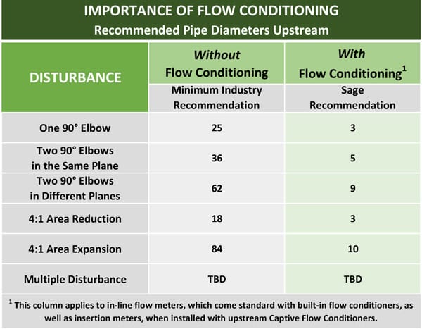
Flow conditioners are standard in the Sage Inline flow meters, 1/2″ and larger, and are available as assemblies for Sage Insertion flow meters. The chart displayed provides examples of the suggested straight run to assure that there are no flow disturbances at the measurement point.
Captive Flow Conditioners
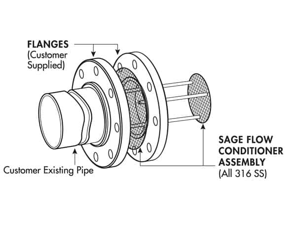
Sage recommends Captive Flow Conditioners for Sage insertion-style flow meters in installations where the recommended straight run is not available. When using these conditioners it is essential that the probe is situated precisely one pipe ID diameter (i.e., 4” in a 4” pipe; 6” in a 6” pipe, and so on) downstream of the Captive Flow Conditioning assembly, or errors occur.
Probe Insertion Guideline
Insertion styles are available through with a standard 1/2″ OD probe support assembly; 3/4″ is also available. Standard probe lengths are 6″, 12″, 15″, 18″, 24″, 30″, 36”, and 48″. A common method of mounting the probe assembly through a pipe wall or duct (if ambient air) is with a compression fitting (STCF05). A Sage valve assembly (SVA05) is useful and highly recommended for pressurized applications or other gases, such as natural gas. Flange mounting is optionally available.
Sage insertion-style flow meters can be assembled and calibrated for use in virtually any size pipe or duct (1” and larger). Sage insertion-style flow meters include a probe assembly that reinforces the sensing component (a self-heated flow sensor and a temperature/reference sensor); a sensor drive circuit; a microprocessor meter board, and transmitter enclosure.

The probe must be inserted into the correct point in the process gas flow conduit to permit the gas to flow through the sensor “window” across the sensor portion. Position the “sensing point” or active portion of the sensor (0.5″ from the end of the probe) as depicted in the illustration.
Installation Depth
Insert the probe so that the sensor is in the center of the pipe and conform with the proper depth as indicated in the Installation Depth Chart.
Large Duct or Stack Applications
Multiple Sage inline flow meters can be used in large round pipes or ducts larger than 36.” For medium-sized round pipes (18”-36”) two meters may be sufficient. In all cases, Sage recommends contacting Customer Service to assist with applications of this nature.
Refer to our User Manuals webpage for the most recent versions and download the model that interests you.
Other topics from the Sage Prime Manual you many be interested in are:
How to Install and Mount my Sage Prime Thermal Mass Flow Meter?
Correction Factors for Biogas Variation From Original Calibration