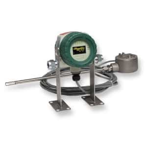
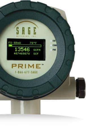
The following troubleshooting guide is from the Sage Prime SIP User Manual. This online source is provided for quick and easy online access to help troubleshoot and correct potential issues experienced with the mass flow meter.
Common Diagnostics for Sage Prime

You may want to download a full manual by clicking the PDF link here.
My Sage meter display failed (or the pixels are incredibly dim).
Contact the factory. Certain types of failures are under long-term warranty. Please note that the 4-20 mA will still function normally.
The meter display is fading or partially fading.
Consider the following:
-
- Some fading, particularly with characters that frequently light up, is expected. The flow meter will still function correctly, and accuracy and outputs are not affected.
- In extreme cases, please message us for replacing the display.
- In 2009 Sage modified the Prime to incorporate a built-in photocell. The photocell adjusts the display brightness with ambient lighting. The brighter the surrounding light, the more brilliant the display. Lower ambient lighting, such as a factory environment, will dim the screen. The screen will be faintest if operated in low ambient light or at night. The photocell circuit extends the life of the screen and minimizes fading.
- In 2010, Sage integrated another improvement to extend the life of the display. The built-in photocell senses motion, which automatically switches the display from Screen Saver mode to Normal mode.
- Screen Saver mode disabled starting in 2016.
I am getting erratic readings on my Sage meter.
If a large motor, generator, or variable frequency drive (VFD) is near the enclosure, analog noise in the circuitry may be temporarily corrupting the data.
We suggest that you:
-
- If a power-restart temporarily solves the problem, the noise is likely the problem’s source.
- To prevent subsequent occurrences, if it is a remote-style meter, move the enclosure as far away as possible from the noise source (the motor or VFD).
- If you have an integral-style meter, mount the meter in a different location (further from the source) or move the basis of the noise away from the meter.

I am getting erratic readings on my remote-style Sage meter.
Another possible cause of erratic readings or climbing readings is analog noise is induced into the remote cable.
We suggest that you:
-
- Be sure that the remote cable is installed in a metal conduit and grounded only on the transmitter end.
- Avoid coiled cable, especially if it is not in metal conduit.
- If extra cable exists, move the line as far away, as possible, from any source of analog noise (e.g., motors or VFDs).
My Sage meter is reading zero continuously, or full-scale continually, or the temperature reading is abnormally low (like hundreds of degrees below zero).
Consider the following possible causes and corrective actions:
-
- A wire is likely loose. In rare cases, a sensor could fail if a standard sensor (HT01 or HT02 sensor) exceeds a process temperature of 450˚F).
- Check for continuity to ensure that the wiring is making contact at the terminals of the junction box.
- Verify that the electronics and the sensor serial numbers are the same. Note: the sensor’s serial number displays when powering up, right after initializing on display. If the serial number does not match the junction box labels, it will affect calibration. The sensors and electronics are a matched pair, and mixing them will cause false readings. Additionally, metal serial number tags are on both the electronics and the junction box. They must have identical serial numbers.
- Use the junction box to check if a sensor has failed on a remote-style meter. Power down (shut off power) the meter. You do not need to remove the probe from the pipe. Refer to page 29.
- Use an ohmmeter to check the sensor leads of the flow sensor. Refer to the junction box drawing. Disconnect the red wires on the factory side to isolate and determine the resistance. If the reading is infinity or a short, the sensor failed.
- Check the temperature sensor. Disconnect the white wires on the factory side to isolate and measure the resistance. If there is an infinity or a short, the sensor burned out. Note: usually, the sensors read around 110 ohms at 70˚ F. At higher temperatures, they should have higher resistance, but both sensors should have a similar reading.
- On an integral-style meter (SIP), there is no junction box. In this case, refer to the Prime Integral Terminals on page 26 and check the sensor wires. Remove the appropriate wires first (a red pair for flow, then a white pair for temperature). Measure their resistance, and if it is reading infinity or short, it means the sensor failed.
My Sage mass flow meter is railing (pegging) or reading high.
Consider the following possible causes and corrective actions:
-
- Do you have a good straight run? Is it possible that the flow profile is disturbed, causing the errors?
- If the upstream pipe is smaller than the meter flow body or if a valve is too close upstream to the meter, it is possible to have a jet effect.
- Are you following the Probe Insertion Guideline?
- If the sensor is inserted in reverse (i.e., the “upstream” mark is facing downstream), the meter may over-report (or under-report) by as much as 30%.
- If the sensor is not aligned correctly, with “upstream,” a rotation more significant than ± 5 degrees may cause a change in the reading (> ± 5 degrees and < ± 20 degrees causes the meter to over-report; a more significant rotation blocks the sensor and causes the meter to under-report).
- Is there a downstream valve too close to the meter? The flow may be reflecting.
- Could water droplets be condensing out of the gas stream? If so, it could cause the output to spike, but if droplets are near-continuous, the output may rail.
- Could it be that the meter is miswired? It may especially be true in a remote style application.
- Water droplets condensing on the inside of the pipe wall that roll down or hit the sensor can cause the output to spike. If the droplets are near-continuous, the output may rail. Note: Sage recommends installing the sensor probe at a 45˚ angle from vertical (see drawing on page 82 of the manual).
- It is possibly caused by water droplets condensing out of the gas stream and filling the cavity containing the sensing elements (usually due to probes mounted below horizontal in saturated pipes).
- The sensor may be contaminated. Remove the probe, wipe off or clean with a solvent. Reinsert.
- Are you using a different gas or gas mix than the meter was specified and calibrated?
- If you have a remote style meter (SRP), be sure the serial numbers on the junction box and remote electronics are identical (if not, calibration errors are inevitable). Verify that the junction box serial number tag has identical serial numbers to the tag on the remote enclosure.
- The meter may appear to be reading high if the user compares Sage flow meter readings (SCFM) to an uncorrected volumetric device (ACFM). For example, at constant volume, a decrease in gas temperature will increase the mass flow (SCFM). That is entirely normal.
My Sage mass flow meter is reading low.
Consider the following:
-
- Do you have a short straight run? Is the flow profile disturbed and causing errors?
- Do you have a poor upstream flow profile (i.e., insufficient upstream straight run)?
- Did you follow the probe insertion guideline when installing the unit?
- If the sensor is inserted in reverse (“Upstream” mark is facing downstream), the meter may over-report (or under-report) by as much as 30%.
- If the sensor is not aligned correctly, with the “Upstream” mark facing upstream, a rotation greater than ± 5 degrees may cause a change in the reading. Greater than ± 5 degrees and less than ± 20 degrees causes the meter to over-report; a more significant rotation blocks the sensor and causes the meter to under-report).
- The sensor may be contaminated. Remove the probe, wipe off or clean with a solvent. Reinsert.
- Are you using a different gas or gas mixture than the meter was specified and calibrated?
- If you have a remote style meter (SRP), make sure the serial numbers of the junction box and remote electronics match. If they do not, calibration errors are inevitable. To confirm, verify that the junction box serial number matches the remote enclosure.
- The meter may appear to be reading low if the user compares Sage flow meter readings (SCFM) to an uncorrected volumetric device (ACFM). For example, at constant volume, an increase in gas temperature will lower the mass flow (SCFM). That is entirely normal.
- In most models, the totalizer will not start counting for 10 seconds after power-up, and flow data will not accumulate during this time.
- Do you have a sufficient power supply? Most products require a minimum of 100 mA.
- Alternatively, do you have an excessive load on the 4-20 mA? When checking if the problem is related to the 4-20 mA output device, temporarily remove the device then see if the display reads as expected.
My totalizer can take up to 10 seconds to update its reading when my flow meter is first powered up or a channel is changed.
This slight delay is entirely reasonable.
My display does not have power.
Consider the possibility that the meter was miswired.
The meter’s 4-20 mA output is not tracking the display flow rate.

Consider the following:
-
- In regular operation (self-powered), B4 and B5 (See pages 21 and 22 in the manual) must be jumpered to supply power to the loop.
- In externally powered mode, remove the jumper. Verify that 9 to 27 V DC is supplied to externally power the loop as per page 20 and pages 27 and 28 for HART units.
My unit has HART communications, and the 4-20 mA output is always at 4 mA.
Consider the possibility that the poll address is not set to 0.
Other topics from the Sage Prime Manual you many be interested in are:
How to Install and Mount my Sage Prime Thermal Mass Flow Meter?
Flow Profile and Installation Considerations for Insertion Flow Meters
Correction Factors for Biogas Variation From Original Calibration
Image by Alexas_Fotos from Pixabay

