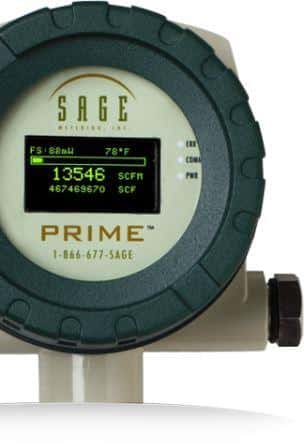
The following post serves as an online resource to provide MODBUS protocol and function codes for the Sage Prime thermal mass flow meter.
Modbus Protocol
Sage Prime meters support communication with other devices by the use of MODBUS protocol using RTU transmission mode. The Modbus protocol defines a message structure that controllers recognize and use, regardless of the type of communication networks. Modbus establishes a standard format for the layout and contents of message fields. Transactions use a master/slave communication where one device, the master, initiates transactions (called queries). The other devices, also known as slaves, provide the requested data to the master and take action demanded in the query. The Sage Meters function as slaves to other Modbus mechanisms and default to 19200-8-E-1. However, the following modes may also be software selectable:
-
- 9600-8-N-1 (Baud-Bits-Parity-Stop)
- 9600-8-E-1
- 9600-8-O-1
- 19200-8-N-1(1)
- 19200-8-E-1 (Default)
- 19200-8-O-1
Message Framing
Messages start with a silent interval of at least 3.5 character times followed by four fields and followed by another silent interval of at least 3.5 character times. The first field contains the device address. The second field contains the function code. The third field includes the data and byte counts. The fourth field has the CRC value.

Refer to Section F of the Sage Prime SIP User Manual for:
-
- Modbus Register Listing
- Function Codes supported by Sage Prime
- Sage Register Output Format
- Sage Addresser Typical Printout
(1) Parity on the Wireless Devices manufactured by Obvius is “None” rather than “Even.” The Sage default is 19200-8-E-1. Change to 19200-8-N-1 for the Obvius Modhoppers and related wireless devices.
Other topics from the Sage Prime Manual you may be interested in are:
How to Install and Mount my Sage Prime Thermal Mass Flow Meter?
Flow Profile and Installation Considerations for Insertion Flow Meters
Correction Factors for Biogas Variation From Original Calibration

